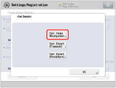
Correct Image Misalignment
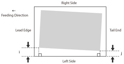
If the printed image is skewed, you may be able to correct the misaligned image by justifying margins of 'i' ,which is the distance from the left edge of the paper to the printing area, and 'j'.
1.
Press  .
.
.2.
Press [Preferences] → [Paper Settings] → [Paper Type Management Settings].
3.
Select the paper type that you want to edit from the list → press [Details/Edit].
4.
Press [Change] for <Adjust Image Position>.
5.
Press [Set Details] → [Corr. Image Misalignment].
If you want to enter the values of the test page you measured manually:
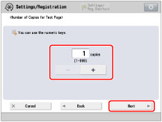
Press [Output Test Page].
Enter the number of test page to make → press [Next].
|
NOTE
|
|
If the image position varies greatly, the accuracy of correction may be improved by printing several test pages and using an average of the measured length.
|
Select a paper source that contains a custom paper size → press [Start Printing].
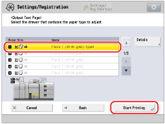
The test page is printed.
Measure the length of the 'i' and 'j' marks on the test page.
The mark 'i' is printed on the left side lead edge and the mark 'j' is printed on the left side tail end of the feeding direction.
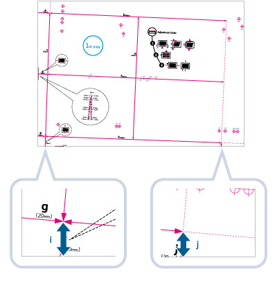
Example: 'i' = 21.0 mm, and 'j' = 20.5 mm
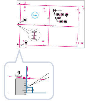
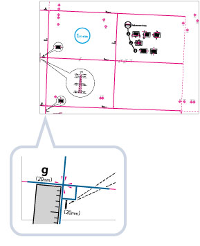
Measure the length of the 'i' and 'j' marks correctly as shown below.
|
Correct
|
Incorrect
|
 |
 |
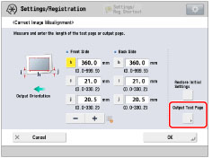
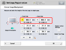
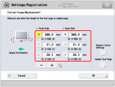
Return to the <Correct Image Misalignment> screen → enter the measured length of [i] and [j] for front and back sides.
Using the following two numerical values and "h = 360.0", a device adjusts so that the printing area and the paper may become parallel.
|
[i]:
|
Enter the measured length of 'i' mark on the test page.
|
|
[j]:
|
Enter the measured length of 'j' mark on the test page.
|
Following the example, enter 21.0 for 'i' and 20.5 for 'j'.
The difference between 'i' and 'j' (0.5 mm) is corrected.
Press [OK].
Print a test page again and check the image position as needed. If you need to make a further adjustment, repeat steps above.
If you correct the position using any printed images:
Check the image position on the output paper.
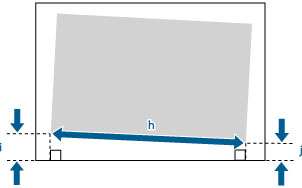
Example: 'h' = 300.0 mm, 'i' = 19.0 mm, and 'j' = 18.0 mm
Measure the following length on the output paper and enter the measured length.
Using the following three numerical values, a device adjusts so that printing area and a paper may become parallel.
|
[h]:
|
Enter the measured length of the left side on the printing area.
|
|
[i]:
|
Enter the measured length from the left side lead edge of the printing area to the left side edge of the paper.
|
|
[j]:
|
Enter the measured length from the left side tail end of the printing area to the left side edge of the paper.
|
Following the example, enter 300.0 for [h], 19.0 for [i], and 18.0 for [j].
The difference between 'i' and 'j' (1.0 mm) is corrected.
Press [OK].
Print a test page again and check the image position as needed. If you need to make a further adjustment, repeat steps above.
6.
Press [OK] → [OK].
|
NOTE
|
|
To restore the accumulated value, press [Restore Initial Settings].
If register marks are printed on the output paper, the printed area is equal to the area inside the register marks.
|