Inserting Polygons
With Desktop Editor, you can insert a polygon into a document as an annotation.
1.
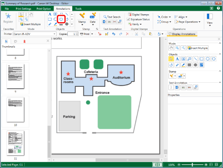
Click  (Polygon) on the ribbon.
 (Polygon) on the ribbon.
Or, click  (Polygon) on the Details Window.

The properties of the polygon are displayed on the Details Window.
|
NOTE
|
|
If the Details Window is not displayed, see the following.
This operation can also be performed with the tool buttons on the toolbar. If tool buttons are not displayed on the toolbar of Desktop Editor, see the following to display them.
You can also insert polygons multiple times. For more information, see the following.
|
2.
Configure the properties of the polygon.

|
[Line Style]
|
Select the line style you want to use from the list displayed when you click
|
|
[Line Weight]
|
Set the line thickness. You can specify a line thickness from 0.25 point to 12.00 point. You can also use
|
|
[Line Color]
|
Select the line color you want to use from the list displayed when you click
|
|
[Shape Fill]
|
Select the color you want to use to fill from the list displayed when you click
|
|
[Transparency]
|
The slider position and the numeric value indicate the degree of transparency of the polygon. To change the degree of transparency, move the slider to the left or right, or enter a numeric value. You can also use
|
|
NOTE
|
|
If [No Line] is selected in [Line Style], drawn lines are displayed as a solid line in light blue.
If [Cloud (Small)] or [Cloud (Large)] is selected in [Line Style], solid lines are displayed for the frame of the annotation when you move a vertex.
If you select [More Colors] in [Line Color] or [Shape Fill], the [Color] dialog box is displayed and you can set a color that is not listed in [Line Color] or [Shape Fill].
Properties can also be set from ribbon commands or toolbar tool buttons. For information on the commands and tool buttons that can set properties, see the following.
|
3.
Move the mouse pointer to the Work Window.
The shape of the mouse pointer changes to  .
.
|
NOTE
|
|
To cancel the insertion process, do one of the following.
Click
 (Select Object) on the ribbon (Select Object) on the ribbonClick
 (Select Text) on the ribbon (Select Text) on the ribbonClick
 (Grab Mode) on the ribbon (Grab Mode) on the ribbonClick the command selected on the ribbon again
Click
Click
Click
Click the selected button on the Details Window again
Press the [Esc] key on the keyboard
|
4.
Click the Work Window.
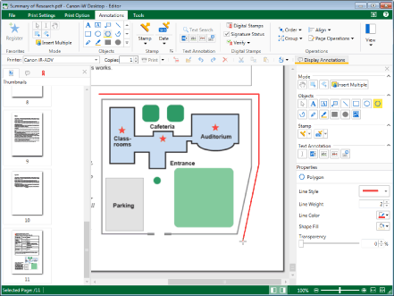
The position you clicked becomes the first vertex.
5.
Click the location where you want to create a vertex.

Each time you click the mouse, the vertices are joined with straight lines.
|
NOTE
|
|
You can press the [BACKSPACE] key on the keyboard to cancel a vertex you just made.
You can create horizontal vertices, vertical vertices, and vertices at 45 degree angles by clicking the mouse pointer while holding down the [Shift] key on the keyboard.
You can press the [Esc] key on the keyboard to clear all the specified vertices.
|
6.
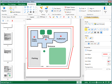
Create three or more vertices, and click near the first vertex you created.
Or, follow one of the steps described below.
Create three or more vertices, and press the [Enter] key on the keyboard
Create two or more vertices, and double-click the mouse when creating the final vertex.

The polygon is created.
|
NOTE
|
|
The following occurs if you perform an operation that prevents additional vertices from being specified, such as clicking somewhere other than the Work Window while drawing.
If you have specified three or more vertices, the polygon is fixed.
If you have specified two or fewer vertices, the specified vertices are cleared.
|
7.
Click on the Work Window outside the polygon you inserted to deselect the polygon.