Correct Distortion (Parallelogram)
This setting enables you to correct the image shape by equalizing the length from the 'a' and 'g' to the lead edge of the paper when the image is printed like a parallelogram.
NOTE |
You can also make the adjustment by using the guide sheet. (See "Adjusting the Image Position Using the Guide Sheet.") |
1.
Press  .
.
.2.
Press [Preferences] → [Paper Settings] → [Paper Type Management Settings].
3.
Select the paper type that you want to edit from the list → press [Details/Edit].
4.
Press [Change] for <Adjust Image Position>.
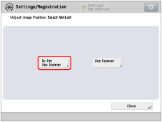
5.
Press [Do Not Use Scanner].
6.
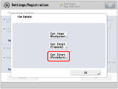
Press [Set Details] → [Corr. Distort. (Paralellgrm)].
If you want to enter the values of the test page you measured manually:
NOTE |
To adjust the image position on long sheets, print out a long sheet test page. The adjustment can be made more efficiently than with the test page printed out by [Output Test Page] under <Correct Distortion (Parallelogram)>. (The long sheet test page is available from the online manual site.) |
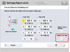
Press [Output Test Page].
Enter the number of test page to make → press [Next].
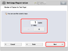
NOTE |
If the image position varies greatly, the accuracy of correction may be improved by printing several test pages and using an average of the measured length. |
Select a paper source that contains a custom paper size → press [Start Printing].
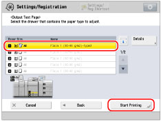
The test page is printed.
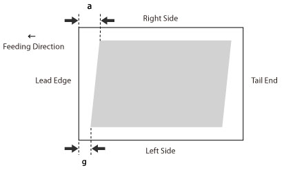
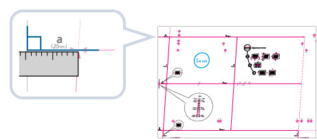
Measure the length of the 'g' and 'a' marks on the test page.
The mark 'g' is printed on the left side lead edge, and the mark 'a' is printed on the right side lead edge of the feeding direction.
Standard size | Long sheet |
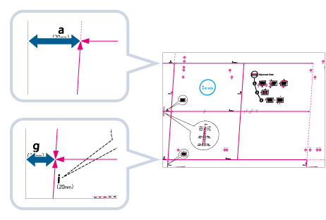 |  |
Example: 'g' = 20.5 mm, and 'a' = 21.0 mm
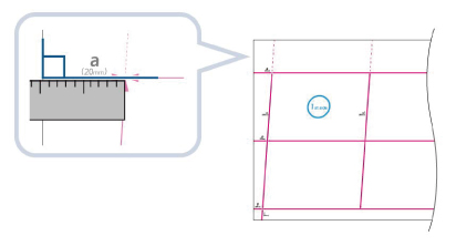
Measure the length of the 'g' and 'a' marks correctly as shown below.
Standard size | Long sheet |
 |  |
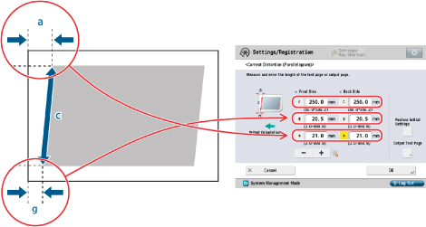
Return to the <Correct Distortion (Parallelogram)> screen → enter the measured length of [g] and [a] for front and back sides.
Using the following two numerical values and "c = 250.0", a device adjusts the length to correct distortion on the printing area.

[g]: | Enter the measured length of 'g' mark on the test page. |
[a]: | Enter the measured length of 'a' mark on the test page. |
Following the example, enter 20.5 for [g] and 21.0 for [a].
The difference between 'g' and 'a' (0.5 mm) is corrected.
Press [OK].
Print a test page again and check the image position as needed. If you need to make a further adjustment, repeat steps above.
If you correct the position using any printed images:
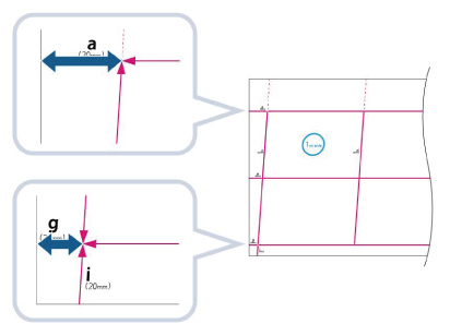
Check the image position on the output paper.
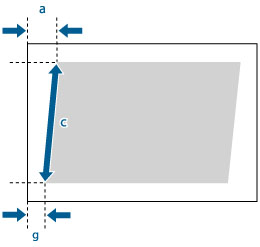
Example: 'c' = 250.0 mm, 'g' = 20.5 mm, and 'a' = 21.0 mm
Measure the following length on the output paper and enter the measured length.
Using the following three numerical values, a device adjusts the length to correct distortion on the printing area.
[c]: | Enter the measured length from the left side lead edge of the printing area to the right side lead edge of the printing area. |
[g]: | Enter the measured length from the left side lead edge of the printing area to the lead edge of the output paper. |
[a]: | Enter the measured length from the right side lead edge of the printing area to the lead edge of the output paper. |
Following the example, enter 250.0 for [c], 20.5 for [g], and 21.0 for [a].
The difference between 'g' and 'a' (0.5 mm) is corrected.
Press [OK].
Print a test page again and check the image position as needed. If you need to make a further adjustment, repeat steps above.
7.
Press [OK] → [OK].
NOTE |
To restore the accumulated value, press [Restore Initial Settings]. |