85CL-00U
How to Fix Misalignment of Images
If the following troubles often occur, the machine may have alignment problems. Check the procedures below.
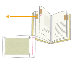
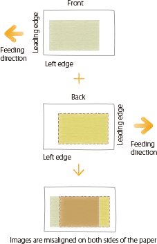
The register marks on one side of a printed sheet do not match those on the other side.
The thumb indexes (*) on the printed pages are not aligned.
The image is not printed within the register marks.
NOTE
You may not be able to correct misalignment that is less than 1.0 mm (1/25").
The machine decides the printing start position based on the leading edge of the paper. After the front side of the paper is printed, the paper is reversed and the back side of the paper is printed from the trailing edge. Because of this, the position where printing starts may be slightly different on opposite sides of the paper.
Eliminating the Basic Causes of Misalignment
Find the answers to your questions about how to solve your problems.
Is the paper cut correctly?
If the paper is not uniform in size and shape, the margins around the image may be different on each page. If the paper is not cut square, the images may be skewed when they are printed.
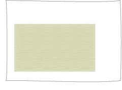
Image is printed near the edge of the paper because the paper size was not set in advance.
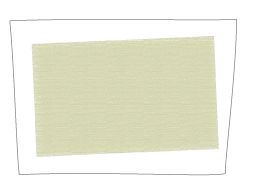
Printed image is skewed because the edges of the paper are not square.
Remedy
Use a different batch of paper that has been cut correctly.
If you cut the paper yourself, measure it and confirm it is the correct size.
Changing Settings on the Machine According to Paper Characteristics
Automatic Adjustment
You can perform periodic automatic adjustment of the image position at any point during the printing process for the custom paper type.
IMPORTANT
Do not use this function with paper that has logos or patterns already printed on it (preprinted paper) or if the paper sheets are dirty.
This function is available only when the Sensing Unit is attached.
NOTE
While printing a job of a large amount of pages, you can perform adjusting the image position differences which occur during the job. When the Sensing Unit is Attached
1
Press  → [Preferences] → [Paper Settings] → [Paper Type Management Settings] → Select the paper type that you want to edit from the list → press [Details/Edit] → [Change] for <Adjust Image Position>.
 → [Preferences] → [Paper Settings] → [Paper Type Management Settings] → Select the paper type that you want to edit from the list → press [Details/Edit] → [Change] for <Adjust Image Position>.
2
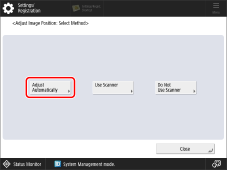
Press [Adjust Automatically].
3
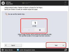
Set the number of test pages you want to print, and then press [Next].
NOTE
If you want to prioritize accuracy, we recommend setting the number of test pages to 10.
4
Select the location of the paper you want to adjust, and then press [Start Adjusting].
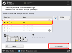
The test pages are printed, and the window shown in step 1 reappears on the screen after the adjustment procedure is completed.
If Using the Scanner
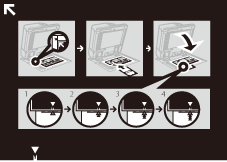
If the images on the front and back sides are misaligned with each other and you want to adjust easily, you can adjust the alignment of the images by scanning the test pages with the guide sheet.
Guide Sheet
Test Page
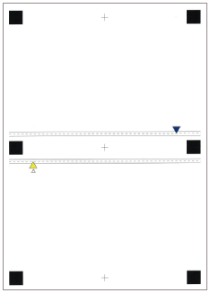
(Front Side)
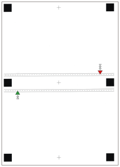
(Back Side)
Before adjustment with the guide sheet

Clean the platen glass and the underside of the feeder.
 "Maintenance" > "Routine Cleaning" > "Cleaning the Platen Glass" in the User's Guide
Before adjustment, print the guide sheet (A3 or 11" x 17") under the following conditions. Accurate adjustment may not be possible if the guide sheet is not printed correctly.
Select the same size as the guide sheet.
Use paper with a weight of more than 200 g/m2 (74 lb cover).
Set the zoom ratio as 100%.
We recommend that the test page is printed to the recommended paper The adjustment may not be performed correctly on the paper that has ruggedness on surface (such as a textured paper, etc.).
If the position of the image cannot be adjusted correctly by [Use Scanner], adjust the position of the image by [Do Not Use Scanner].
The Duplex Color Image Reader Unit-P (optional) is required for this adjustment.
1
Press  → [Preferences] → [Paper Settings] → [Paper Type Management Settings] → Select the paper type that you want to edit from the list → press [Details/Edit] → [Change] for <Adjust Image Position>.
 → [Preferences] → [Paper Settings] → [Paper Type Management Settings] → Select the paper type that you want to edit from the list → press [Details/Edit] → [Change] for <Adjust Image Position>.
2
Press [Use Scanner].
To Print the Guide Sheet

1
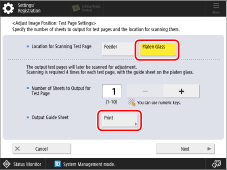
Select [Platen Glass] in <Adjust Image Position: Test Page Settings>, and press [Print] in [Output Guide Sheet].
2
Select the paper source where the paper you use is placed → press [Start Printing].
The guide sheet is printed.
3
Enter the number of test page to make → press [Next].
NOTE
The larger the number of output test pages, the more accurate the adjustment is.
If specifying multiple output test pages, make sure that all of the test pages are scanned in the order they are output. If the order is changed or the scanning process is not performed successively, the adjustment may not be made correctly.
To obtain a highly precise output result, leave the output test pages for 10 minutes before you start scanning, so that they can fully acclimatize to the conditions. Test pages on easily stretchable paper may expand or contract if scanned immediately after output, which may affect the scan result.
To obtain a highly precise correction result easily, set the number of output test pages to one, complete the adjustment, and then adjust [Front Side] and [Back Side] of <Lead Edge (e) Alignment>. These settings and adjustments allow you to obtain a correction result similar to that obtained by scanning multiple test pages.
To align the position of the front and back surfaces for the user image, press [Do Not Use Scanner] to adjust additionaly the position of the image.
4
Select the paper source that contains the paper type to adjust → press [Start Printing].
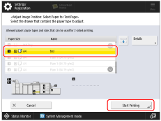
The test page is printed.
5
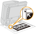
Place the guide sheet on the platen glass with the arrows of the sheet and on the platen glass aligned.
6
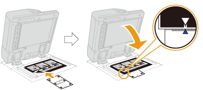
Align the mark  on the test page for the first scan operation with the mark on the guide sheet.
 on the test page for the first scan operation with the mark on the guide sheet.
7
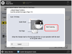
Close the feeder → press [Start Scanning].
NOTE
Open and close the feeder gently. Make sure that the guide sheet remains aligned when closing the feeder.
8
Turn the test page upside down, and then align the mark  on the test page for the second scan operation with the mark on the guide sheet → press [Start Scanning].
 on the test page for the second scan operation with the mark on the guide sheet → press [Start Scanning].
9
Turn the test page over, and then align the mark  on the test page for the third scan operation with the mark on the guide sheet → press [Start Scanning].
 on the test page for the third scan operation with the mark on the guide sheet → press [Start Scanning].
10
Turn the test page upside down, and then align the mark  on the test page for the fourth scan operation with the mark on the guide sheet → press [Start Scanning].
 on the test page for the fourth scan operation with the mark on the guide sheet → press [Start Scanning].
11
Adjustment is complete.
If you have specified multiple output test pages, repeat steps 6 to 10 for all of the output test pages. In this case, adjustment is complete when all of the test pages have been scanned.
Make sure that the test pages are scanned in the order they are output.
Make sure that the test pages are scanned in the order they are output.
If Not Using the Scanner
If you are not using the scanner, change the settings to meet paper characteristics.
NOTE
You cannot change the settings for a 'standard' type of paper that is indicated with the paper-without-pencil icon ( ) on the screen. In this case, duplicate a 'standard' type of paper to make a 'custom' type of paper that is indicated with the paper- and-pencil icon (
 ), and change the settings for it. After specifying the settings for the custom type of paper you made, press
  → [Preferences] → [Paper Settings] → [Paper Settings], and change a type of paper for the paper source to that paper.
 ) on the screen. In this case, duplicate a 'standard' type of paper to make a 'custom' type of paper that is indicated with the paper- and-pencil icon (
 ), and change the settings for it. After specifying the settings for the custom type of paper you made, press
  → [Preferences] → [Paper Settings] → [Paper Settings], and change a type of paper for the paper source to that paper.
Registering the Measured Value of the Paper
If you want to print the image within a specified area, you need to register the correct paper size in advance. Measure the paper size and register the value.
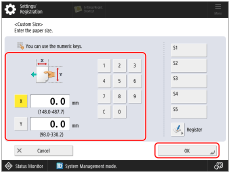
Press  → [Preferences] → [Paper Settings] → [Paper Type Management Settings] → select the brand of paper in which the image is misaligned → press [Details/Edit] → [Change] for <Size> → [Custom Size] → enter the measured value.
 → [Preferences] → [Paper Settings] → [Paper Type Management Settings] → select the brand of paper in which the image is misaligned → press [Details/Edit] → [Change] for <Size> → [Custom Size] → enter the measured value.
 "Paper Type Management Settings" in the User's Guide > see "Size" under the subsection "Items that can be specified"
Adjusting the Position of the Image
You can adjust the position in which the image is actually printed.
1
Press  → [Preferences] → [Paper Settings] → [Paper Type Management Settings] → select the brand of paper in which the image is misaligned → press [Details/Edit] → [Change] for <Adjust Image Position> → [Do Not Use Scanner].
 → [Preferences] → [Paper Settings] → [Paper Type Management Settings] → select the brand of paper in which the image is misaligned → press [Details/Edit] → [Change] for <Adjust Image Position> → [Do Not Use Scanner].
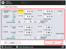
2
Print a test page.
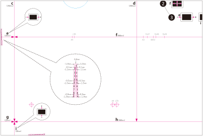
3
Adjust the position of the image in the sequence shown below.

4
Print another test page and hold it up to a light to see if the  (register marks) are in the same position on both sides of the paper.
5
If the  (register marks) are not aligned, adjust the position of the image again in the sequence shown below.

NOTE
Print about ten copies of the test page, and then measure the final page that is printed. This is done to improve accuracy, because the position of the images that are printed first is inconsistent. If the humidity is high, print about 30 copies of the test page and measure the final page.
If you are adjusting the position of the image on coated paper or heavy paper that is more than 250 g/m2 (92.5 lb Cover), print three to five test pages and use the average value. This is done because the position of the image on heavy or coated paper is inconsistent.
Use the marks for each paper size when checking for misalignment of images. For example, if the test page is A3, use the  register mark to check for misalignment.
If you change the value in [Adj. Secondary Transfer Voltage], be sure to adjust the zoom ratio of the image.
 "Paper Type Management Settings" > "Adjusting the Image Position" in the User's Guide
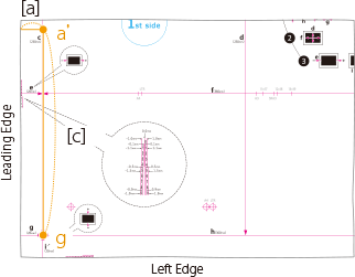
How to Correct Skew and Parallelogram/Trapezoid Distortion on a Small Test Page

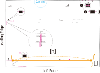
Skew Correction
If the test page is so small that <j> is not on the page, add an arbitrary mark <j'> anywhere on the red line <h>. Then, enter the distance from <j'> to the left edge of the paper in [j]. Enter the distance from <i> to <j'> in [h].
Trapezoid Distortion Correction
If the test page is so small that the distances b and h cannot be measured, add <c'>, <b'> and <h'> as shown in the illustration on the right. Enter these distances in [C], [B] and [h] respectively.
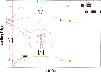
Parallelogram Distortion Correction
If the test page is so small that <a> is not on the page, add an arbitrary mark <a'> on the red line <c>. Enter the distance from <a'> to the leading edge of the paper in [A]. Enter the distance from <g> to <a'> in [C].
Changing Print Settings on the Printer Driver
If you still have misalignment problems after you follow the procedures in steps 1 and 2, you can adjust the image position by changing the print job settings on the printer driver. The procedure below is for imagePRESS Server.
Printing One Page on One or Each Side of Paper
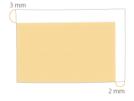
For example, if the printing results are different from what you expected as shown below, use the following procedure to change the settings. These settings can be changed for each job.
What you wanted to print
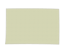
Front
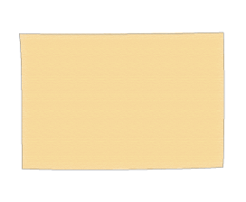
Back
What actually was printed
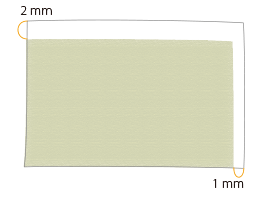
Front
Back
1
Double-click the job in Command WorkStation on the imagePRESS Server.
[Job Properties] is displayed.
2
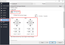
Click the [FINISHING] tab → select [Image shift] and enter the value in millimeters (inches) to move the image horizontally (X direction) and vertically (Y direction).
In this case, enter the value for each direction as shown below.
[Front] X: 1.00 mm, Y: 2.00 mm [Back] X: 2.00 mm, Y: 3.00 mm
3
Click [Print].
The machine starts printing. Check the printed page and confirm that the misalignment problem is solved, and then start printing.
Printing Multiple Pages on One or Each Side of Paper
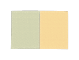
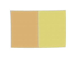
For example, if the printing results are different from what you expected as shown below, use the following procedure to change the settings. These settings can be changed for each job.
What you wanted to print
Front
Back
What actually was printed
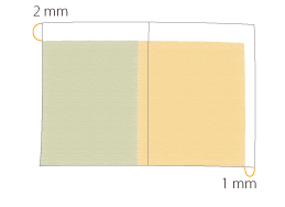
Front
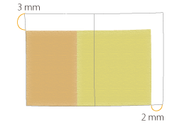
Back
1
Double-click the job in Command WorkStation on the imagePRESS Server.
[Job Properties] is displayed.
2
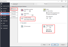
Click the [LAYOUT] tab → select [Normal] → <Short edge binding> for [2-sided printing] and <2> for [Pages per Sheet].
NOTE
If you select [Booklet], not [Normal], you cannot select [Image shift] in step 3. If you want to make a booklet, you need to print the job and then saddle stitch it separately.
3
Click the [FINISHING] tab → select [Image shift] and enter the value in millimeters (inches) to move the image horizontally (X direction) and vertically (Y direction).
In this case, enter the value for each direction as shown below.
[Front] X: 1.00 mm, Y: 2.00 mm [Back] X: 2.00 mm, Y: 3.00 mm

4
Click [Print].
The machine starts printing. Check the printed page and confirm that the misalignment problem is solved, and then saddle stitch the booklet separately if you want to make a booklet.
NOTE
You cannot move the image on each page after the imposition of images is completed. The laid out images on the two pages move together as a single image.
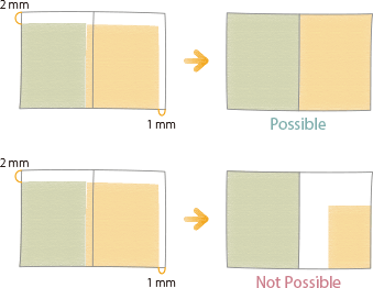
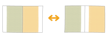
If you select [Booklet] in step 2, you can move the image toward the fore-edge or the gutter of the page as shown in the illustration below. For more information, see the following.
When the Sensing Unit is Attached
When the Sensing Unit is attached, you can set it to detect the print position differences which occur while printing a job of a large amount of pages and correct the differences automatically.
1
Double-click the job in Command WorkStation on the imagePRESS Server.
[Job Properties] is displayed.
2
Click the [IMAGE] tab → select [Image position].
3
Select the adjusting method.
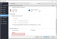
[Print marks on paper margins]

By detecting the markers printed on the margins of paper on which a job is printed, the print positions are corrected.
IMPORTANT
For the necessary width of the margins on which the makers are printed, see the specifications of the printer and the Sensing Unit.
Automatic adjustment is performed by scanning the already printed paper with the Sensing Unit and by reflecting the scanned result to the subsequent pages. Because of this process, if a bundle of paper is switched to another bundle when a paper source is changed or when a new bundle of paper is loaded, the adjustment suitable for the new bundle of paper may not be applied soon.
[Insert test charts with marks]

Select this method when there are not enough margins of the paper on which a job is printed.
The print positions are corrected by scanning the test charts for detecting print positions. The test charts are inserted during a print job after printing a specified number of pages.
The print positions are corrected by scanning the test charts for detecting print positions. The test charts are inserted during a print job after printing a specified number of pages.
IMPORTANT
Do not use this function with paper that has logos or patterns already printed on it (preprinted paper) or if the paper sheets are dirty.
You need to add enough paper sheets to the paper deck to print the adjustment pages.
If a paper jam occurs during a job with automatic adjustment, the adjustment pages may not be printed.
NOTE
Automatic adjustment will not be carried out for any jobs you start by interrupting the job in progress.
Such jobs may not start in the interruption time intervals you set. Keep in mind that the interval setting is merely an estimate.
If you wish to prioritize accuracy by adjusting the interruption intervals, increase the interruption frequency. However, that will also require more adjustment pages and therefore decrease productivity.
The adjustment may not be as effective for jobs where multiple types of paper are used simultaneously.
Configuring the interval for printing the test charts
1
Press  → [Preferences] → [Paper Settings] → [Paper Type Management Settings] → select the paper type you want to edit from the list → press [Details/Edit] → [Change] under [Adjustment Page Interrupt. Interval].
 → [Preferences] → [Paper Settings] → [Paper Type Management Settings] → select the paper type you want to edit from the list → press [Details/Edit] → [Change] under [Adjustment Page Interrupt. Interval].
2
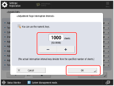
Set a value between 50 and 9999 sheets as the interruption interval for adjustment pages, and then press [OK].
4
Click [Print].