Parts and Their Functions
This section provides you with the names and functions of all the parts of the machine.
For information on optional products, parts and their functions, see "Optional Products/Software."
External View
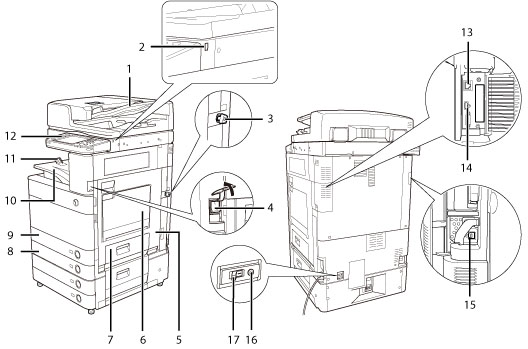
The Duplex Color Image Reader Unit-E1 and Cassette Feeding Unit-AD2 are attached:
_intro_en_UV/b_intro_006_01_f_C.jpg)
|
1.
|
Feeder (Optional)
Originals placed in the feeder are fed one sheet at a time to the platen glass for scanning.
|
|
2.
|
USB Port (1)
Use the USB port to connect a USB device.
|
|
3.
|
Security Key (Optional)
For managing the use of the machine and preventing unauthorized copies.
|
|
4.
|
Main Power Switch
Press to the "I" side to turn the power ON. (See "Control Panel Parts and Functions.")
|
|
5.
|
Main Unit's Right Cover
Open this cover when clearing a paper jam inside the main unit. (See "Clearing Paper Jams.")
|
|
6.
|
Multi-Purpose Tray
Use the multi-purpose tray to feed paper manually, and for loading nonstandard paper stock, such as envelopes. (See "Loading Paper into the Multi-Purpose Tray.")
|
|
7.
|
Paper Drawer's Right Cover
Open this cover when clearing a paper jam in Paper Drawers 1 and 2. (See "Clearing Paper Jams.")
|
|
8.
|
Paper Drawer 2
Holds up to 550 sheets of paper (80 g/m2).
|
|
9.
|
Paper Drawer 1
Holds up to 550 sheets of paper (80 g/m2).
|
|
10.
|
Output Tray
Prints and copies are output to this tray.
|
|
11.
|
Output Paper Tray Guide
Tilt the output paper tray guide up to prevent output papers from falling down.
|
|
12.
|
Control Panel
Includes the keys, touch panel display, and indicators required for operating the machine. (See "Control Panel Parts and Functions.")
|
|
13.
|
LAN Port
Use a LAN cable to connect the machine to a network.
|
|
14.
|
USB Port (2)
Use the USB port to connect external hard disks and other devices to the machine.
|
|
15.
|
USB Connector
Use a USB cable to connect the machine to a computer.
|
|
16.
|
Test Button
Press this button to test the circuit breaker.
|
|
17.
|
Breaker
Detects excess current or leakage current.
|
|
18.
|
LINE 4
Use this port to connect the Super G3 3rd/4th Line Fax Board to the machine.
|
|
19.
|
LINE 3
Use this port to connect the Super G3 3rd/4th Line Fax Board to the machine.
|
|
20.
|
LINE 2
Use this port to connect the Super G3 2nd Line Fax Board to the machine.
|
|
21.
|
LINE 1
Use this port to connect a fax line to the machine.
|
|
NOTE
|
|
The Super G3 3rd/4th Line Fax Board and Super G3 2nd Line Fax Board are optional products. For more information, see "System Configuration."
For information on the optional products required to use the fax function,see "Optional Products Required for Each Function."
|
Internal View
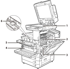
The Duplex Color Image Reader Unit-E1 and Cassette Feeding Unit-AD2 are attached:
|
1.
|
Platen Glass
Use the platen glass when scanning books, thick originals, thin originals, transparencies, etc.
|
|
2.
|
Upper Cover of the Fixing Unit
Open this cover to clear a paper jam in the fixing unit. (See "Clearing Paper Jams.")
|
|
3.
|
Duplexing Unit
Pull out the duplexing unit to clear a paper jam. (See "Clearing Paper Jams.")
|
|
4.
|
Waste Toner Container
Waste toner accumulates here. (See "Replacing the Waste Toner Container.")
|
|
5.
|
Toner Replacement Cover
Open this cover to replace the toner cartridge.
|
|
6.
|
Toner Cartridge
When toner runs out, pull out the toner cartridge, and replace it with a new one.
|
Control Panel Parts and Functions
_intro_en_UV/b_intro_006_01_c_C.jpg)
|
1.
|
Energy Saver key
Press to set or cancel the Sleep mode. Lights when the machine enters the Sleep mode. For more information on the Auto Sleep mode, see "Main Power and Energy Saver Key." |
|
2.
|
Settings/Registration key
Press to specify settings/registration. |
|
3.
|
Counter Check key
Press to display the copy and print count totals on the touch panel display. |
|
4.
|
Clear key
Press to clear entered values or characters.
|
|
5.
|
Stop key
Press to stop a job in progress, such as a scan, copy, or fax (scanning only) job. |
|
6.
|
Edit Pen
Use when operating the touch panel display, such as to enter characters. If you lose the edit pen, contact your local authorized Canon dealer. Do not use an object with a sharp end on the control panel, such as a pencil or ballpoint pen, in place of the edit pen. |
|
7.
|
Start key
Press to start an operation. |
|
8.
|
Main Power Indicator
Lights when the main power is turned ON. |
|
9.
|
Error Indicator
Flashes or lights if there is an error in the machine. When the Error indicator flashes, follow the instructions that appear on the touch panel display. When the Error indicator maintains a steady red light, contact your local authorized Canon dealer. |
|
10.
|
Processing/Data Indicator
Flashes or blinks green when the machine is performing operations, and maintains a steady green light when fax data is stored in memory. |
|
11.
|
Reset key
Press to restore the standard settings of the machine. |
|
12.
|
ID (Log In/Out) key
Press to log in/out when a login service such as Department ID Management or SSO-H has been set. |
|
13.
|
Numeric keys
Press to enter numerical values. |
|
14.
|
Touch Panel Display
The settings screen for each function is shown on this display. Eight function keys are displayed by default. |
|
15.
|
Brightness Adjustment Dial
Use to adjust the brightness of the touch panel display. |
|
16.
|
Volume Settings key
Press to display the screen for adjusting settings, such as the transmission volume and fax sending/receiving alarm volume. |
|
17.
|
Status Monitor/Cancel key
Press to check the status of jobs or to cancel print jobs. Also, press to check status of the machine, such as checking the amount of paper remaining. |
|
18.
|
Quick Menu key
Press to retrieve favorite functions stored in Quick Menu. Also, if you are using authentication, Quick Menu set for each individual user can be displayed. (See "Quick Menu.") |
|
19.
|
Main Menu key
Press to return to the Main Menu screen, such as when you want to switch functions. |
|
NOTE
|
|
For more information on the optional products that can be attached to the machine, see "Optional Products/Software."
|