Parts and Their Functions
This section provides you with the names and functions of all the parts of the machine.
For information on optional products, parts, and their functions, see "Optional Products/Software."
External View
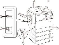
When the Cassette Module-AA1 and Staple Finisher-R1 are attached:
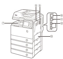
When the Cassette Module-AA1 is attached:
|
1.
|
Main Power Switch
Press to the "I" side to turn ON the machine.
|
|
2.
|
LINE 1
Use this port to connect a fax line to the machine.
|
|
3.
|
LINE 2
Use this port to connect the Super G3 2nd Line Fax Board to the machine.
|
|
4.
|
Feeder
Originals placed in the feeder are automatically fed sheet by sheet to the scanning area. The feeder also automatically turns over two-sided originals to make one- or two-sided copies.
|
|
5.
|
Control Panel
The control panel includes the keys, touch panel display, and indicators required for operating the machine. (See "Control Panel Parts and Functions.")
|
|
6.
|
Paper Drawer 1
Holds up to 550 sheets of paper (80 g/m2).
|
|
7.
|
Output Tray
Prints are output to this tray if the optional Staple Finisher-R1 is not attached.
|
|
8.
|
USB Port (1)
Use the USB port to connect USB memory to the machine.
|
|
9.
|
Right Cover of the Main Unit
Open this cover when clearing a paper jam inside the main unit. (See "Clearing Paper Jams.")
|
|
10.
|
LAN Port
Use an Ethernet cable to connect the machine to a network.
|
|
11.
|
USB Port (2)
Use the USB port to insert a USB cable for connecting to a computer.
|
|
12.
|
USB Port (3)
Use the USB port to connect external hard disks and other devices to the machine.
|
|
13.
|
Multi-Purpose Tray
Use the multi-purpose tray to feed paper manually, and for loading nonstandard paper stock, such as envelopes. (See "Loading Paper into the Multi-Purpose Tray.")
|
|
NOTE
|
|
The Super G3 2nd Line Fax Board is an optional product. For more information, see "System Configuration."
For information on the optional products required to use the fax function, see "Optional Products Required for Each Function."
|
Internal View
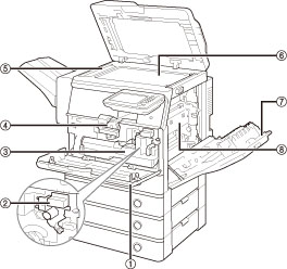
When the Cassette Module-AA1 and Staple Finisher-R1 are attached:
|
1.
|
Front Cover of the Main Unit
Open this cover to replace the toner cartridge, the waste toner container, and the drum unit.
|
|
2.
|
Drum Unit
The unit that applies toner to paper during printing. For more information on handling the drum unit, see "Replacing the Drum Unit."
|
|
3.
|
Waste Toner Container
When the waste toner container becomes full, replace it with a new one. (See "Replacing the Waste Toner Container.")
|
|
4.
|
Toner Cartridge
When toner runs out, pull out the toner cartridge and replace it with a new one. (See "Consumables.")
|
|
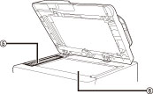
5.
|
Scanning Area
Originals placed in the feeder are scanned here.
|
|
6.
|
Platen Glass
Place originals here when scanning books, heavyweight originals, transparencies, etc.
|
|
7.
|
Right Cover of the Main Unit
Open this cover when clearing a paper jam inside the main unit.
|
|
8.
|
Fixing Unit
If paper is jammed in the fixing unit, remove the jammed paper carefully. (See "Clearing Paper Jams.")
|
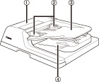
Feeder
|
1.
|
Feeder Cover
Open this cover to remove jammed paper.
|
|
2.
|
Slide Guides
Adjust these guides to match the width of the original.
|
|
3.
|
Original Supply Tray
Originals placed here are automatically fed sheet by sheet into the feeder. Place originals into this tray with the surface that you want to scan face up.
|
|
4.
|
Original Output Area
Originals that have been scanned from the original supply tray are output into the original output area.
|
|
5.
|
Document Feed Scanning Area
Scans documents sent from the feeder.
|
|
6.
|
Platen Glass
Use the platen glass when scanning books, thick originals, thin originals, transparencies, etc.
|
 CAUTION CAUTION |
|
Do not insert your fingers into the gaps around the original supply tray, as your fingers may get caught.
|
|
IMPORTANT
|
|
Be careful not to drop objects, such as paper clips into the gaps, as doing so may cause damage to the machine or cause it to break down.
When using the platen glass to copy or scan thick originals, such as books or magazines, do not press down hard on the feeder.
If the original output area is blocked, originals may get damaged, and printing may not be performed correctly. Therefore, do not place any objects in the original output area.
|
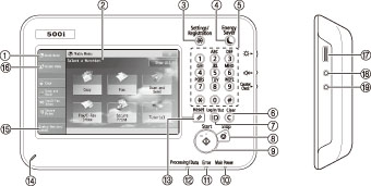
Control Panel Parts and Functions
|
1.
|
[Main Menu]
Press to display the Main Menu screen. If the Main Menu screen is not displayed when using a function, it is necessary to press [Main Menu] before using the function.
|
|
2.
|
Touch Panel Display
The settings screen for each function is shown on this display. Six function keys are displayed by default.
|
|
3.
|
Settings/Registration key
Press to specify settings/registration.
|
|
4.
|
Energy Saver key
Press to set or cancel the Sleep mode. Lights when the machine enters the Sleep mode. For more information on the Auto Sleep mode, see "Main Power and Energy Saver Key." |
|
5.
|
Numeric keys
Press to enter numerical values.
|
|
6.
|
Clear key
Press to clear entered values or characters.
|
|
7.
|
ID (Log In/Out) key
Press to log in/out when a login service such as Department ID Management or SSO-H has been set. |
|
8.
|
Stop key
Press to stop a job in progress, such as a scan, copy, or fax (scanning only) job. |
|
9.
|
Start key
Press to start an operation. |
|
10.
|
Main Power Indicator
Lights when the main power is turned On. |
|
11.
|
Error Indicator
Flashes or lights if there is an error in the machine. When the Error indicator flashes, follow the instructions that appear on the touch panel display. When the Error indicator maintains a steady red light, contact your local authorized Canon dealer. |
|
12.
|
Processing/Data Indicator
Flashes or blinks green when the machine is performing operations, and maintains a steady green light when fax data is stored in memory. |
|
13.
|
Reset key
Press to restore the standard settings of the machine. |
|
14.
|
Edit Pen
Use when operating the touch panel display, such as to enter characters.
|
|
15.
|
[Status Monitor/Cancel]
Press to check the status of jobs or to cancel print jobs. Also, you can check the status of the machine such as the amount of paper remaining in the paper source.
|
|
16.
|
[Quick Menu]
Press to display functions registered in the Quick Menu.
|
|
17.
|
Brightness Adjustment Dial
Use to adjust the brightness of the touch panel display. |
|
18.
|
Volume Settings key
Press to display the screen for adjusting settings, such as the transmission volume and fax sending/receiving alarm volume. |
|
19.
|
Counter Check key
Press to display the copy and print count totals on the touch panel display.
|
Adjusting the Angle of the Control Panel
The angle of the control panel is adjustable as shown below.
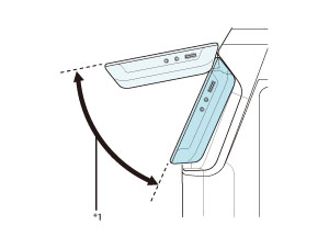
*1: Adjustable Range
|
IMPORTANT
|
|
Do not apply excess force to the control panel when adjusting its angle.
|
|
NOTE
|
|
For more information on the optional products that can be attached to the machine, see "Optional Products/Software."
|