Registering/Editing Custom Paper Types
You can register up to 200 custom paper types, besides the default paper types registered in the machine.
[Paper Type Management Settings] Screen Display
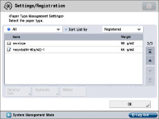
The icons displayed on the screen are as follows:
 : Paper that is registered from [Duplicate] with default settings.
 : Paper that is registered from [Duplicate] with changed settings.
You can select a paper type to display from the paper type selection drop-down list.
[All]: Displays all paper types.
[Standard Type]: Displays only standard paper types.
[Custom Type]: Displays only custom paper types.
|
NOTE
|
|
You can edit only user-registered paper types.
You cannot change the detailed information for paper currently being used for copy/print jobs.
You can sort the paper type list by registration date ([Registered]), name ([Name]), or basis weight ([Basis Weight]) from the Sort List drop-down list.
|
1.
Press  (Settings/Registration).
(Settings/Registration). 2.
Press [Preferences] → [Paper Settings] → [Paper Type Management Settings].
Registering Custom Paper Types:
Select a paper type from the list that closely matches the characteristics of the paper type you want to register → press [Duplicate].
Enter a name → press [OK].
|
NOTE
|
|
When you register the settings for the custom paper type, make sure to change its name. You cannot change the settings of the default paper types registered in the machine.
|
Changing the Name of a Custom Paper Type:
Select the paper type that you want to edit from the list → press [Details/Edit].
Press [Change] for <Name> → enter a name → press [OK].
Press [OK].
Changing the Basis Weight of a Custom Paper Type:
Select the paper type that you want to edit from the list → press [Details/Edit].
Press [Change] for <Basis Weight> → press [-] or [+] to set the paper weight → press [OK].
Press [OK].
|
IMPORTANT
|
|
If you enter a value that is different to the actual weight of the paper, paper jams may occur, and the quality of the image may be adversely affected.
|
Changing the Finishing Type of a Custom Paper Type:
Select the paper type that you want to edit from the list → press [Details/Edit].
Press [Change] for <Finish> → select the finishing type → press [OK].
Press [OK].
|
IMPORTANT
|
|
If you select a finishing type which is different from the actual surface texture of the paper, paper jams may occur, and the quality of the image may be adversely affected.
|
Changing the Type of a Custom Paper Type:
Select the paper type that you want to edit from the list → press [Details/Edit].
Press [Change] for <Type> → select the paper type → press [OK].
Press [OK].
|
IMPORTANT
|
|
If you select a paper type which is different from the actual paper type, paper jams may occur, and the quality of the image may be adversely affected.
|
Changing the Colour of a Custom Paper Type:
Select the paper type that you want to edit from the list → press [Details/Edit].
Press [Change] for <Color> → select the paper colour → press [OK].
Press [OK].
|
IMPORTANT
|
|
If you select a colour which is different from the actual colour of the paper, paper jams may occur, and the quality of the image may be adversely affected.
|
Adjusting the Creep (Displacement) Correction of a Custom Paper Type:
Select the paper type that you want to edit from the list → press [Details/Edit].
Press [Change] for <Adjust Creep Correction>.
Press [ ] or [
 ] to adjust the correction width → press [OK].
] or [] to adjust the correction width → press [OK].Press [OK].
|
NOTE
|
|
For more information on creep (displacement), see "Booklet Mode" and "Booklet Mode."
The value you set here becomes the default correction width when the selected paper type is used for saddle stitching with automatic [Creep Correction].
|
Printing a Test Page to Adjust the Image Position on a Custom Paper Type:
Select the paper type that you want to edit from the list → press [Details/Edit].
Press [Change] next to [Adjust Image Position].
Press [Output Test Page].
Enter the number of copies of a test page.
Select a paper source that contains a custom paper size → press [Start Printing].
The test page is printed.
|
IMPORTANT
|
|
139.7 mm x 182.0 mm to 330.2 mm x 487.7 mm paper can be used for the test pages. Make sure that a sufficient supply of paper is loaded into the machine before starting this procedure.
If you perform test page using paper smaller than A3, the entire image cannot be printed on the paper. Nevertheless, you can read the register mark, because the tail edge you do not have to check is lacking.
|
Adjusting Lead Edge Alignment of the Image on a Custom Paper Type:
Select the paper type that you want to edit from the list → press [Details/Edit].
Press [Change] next to [Adjust Image Position].
Press [Output Test Page].
Select a paper source that contains a custom paper size → press [Start Printing].
The test page is printed.
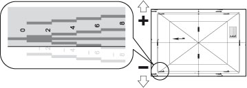
Check the location of the lead edge image on the front side of the test page.
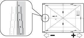
In the above example, the center line of the register mark is outside the lead edge of the test page (center line of the register mark is NOT printed). Follow the procedure described below to adjust the lead edge of the image on the front side of the test page.
Press [Adjust Lead Edge Alignment].
Press [-] or [+] for [Front Side] to input the number of pixels to shift the image.
Input the value from the test page.
Following the example in the procedure described above, input [+4] for [Front Side].
|
[+]:
|
Press when the center line of the register mark is located outside the edge of the test page (the center line of the register mark is NOT printed). The image is shifted to the backwards as seen from the feeding direction of the paper, according to the number of pixels entered.
|
|
[-]:
|
Press when the center line of the register mark is located inside of the edge of the test print. The image is shifted to the forwards as seen from the feeding direction of the paper, according to the number of pixels entered.
|
Turn over the test page → check the lead edge image on the back side of the test page.
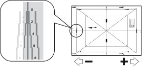
In the above example, the center line of the register mark is inside the lead edge of the test page.
Press [-] or [+] for [Back Side] to input the number of pixels to shift the image.
Input the value from the test page.
Following the example in the procedure described above, input [-6] for [Back Side].
|
[+]:
|
Press when the center line of the register mark is located outside the edge of the test print (the center line of the register mark is NOT printed). The image is shifted to the backwards as seen from the feeding direction of the paper, according to the number of pixels entered.
|
|
[-]:
|
Press when the center line of the register mark is located inside of the edge of the test print. The image is shifted to the forwards as seen from the feeding direction of the paper, according to the number of pixels entered.
|
Press [OK].
Perform the test page again, and check the location of the image.
Repeat the procedure described above until the center line of the register mark aligns with the lead edge of the paper.
Press [Close] → [OK].
|
IMPORTANT
|
|
139.7 mm x 182.0 mm to 330.2 mm x 487.7 mm paper can be used for the test pages. Make sure that a sufficient supply of paper is loaded into the machine before starting this procedure.
If you perform test page using paper smaller than A3, the entire image cannot be printed on the paper. Nevertheless, you can read the register mark, because the tail edge you do not have to check is lacking.
When you open the [Adjust Image Position] screen again after you close that screen by pressing [OK], the values on screen are returned to [0]. Nevertheless the adjusted value is effective. If you repeat steps, read off the value of register marks from new test page and input the new value.
|
Adjusting Left Edge Alignment of the Image on a Custom Paper Type:
Select the paper type that you want to edit from the list → press [Details/Edit].
Press [Change] next to [Adjust Image Position].
Press [Output Test Page].
Select a paper source that contains a custom paper size → press [Start Printing].
The test page is printed.
Check the location of the left edge image on the front side of the test page.
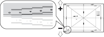
In the above example, the center line of the register mark is outside the left edge of the test page (center line of the register mark is NOT printed). Follow the procedure described below to adjust the left edge of the image on the front side of the test page.
Press [Adjust Left Edge Alignment].
Press [-] or [+] for [Front Side] to input the number of pixels to shift the image.
Input the value from the test page.
Following the example in the procedure described above, input [+4] for [Front Side].
|
[+]:
|
Press when the center line of the register mark is located outside the edge of the test print (the center line of the register mark is NOT printed). The image is shifted to the right as seen from the feeding direction of the paper, according to the number of pixels entered.
|
|
[-]:
|
Press when the center line of the register mark is located inside of the edge of the test print. The image is shifted to the left as seen from the feeding direction of the paper, according to the number of pixels entered.
|
Turn over the test page → check the left edge image on the back side of the test page.
In the above example, the center line of the register mark is inside the left edge of the test page.
Press [-] or [+] for <Back Side> to input the number of pixels to shift the image.
Input the value from the test page.
Following the example in the procedure described above, input [-6] for [Back Side].
|
[+]:
|
Press when the center line of the register mark is located outside the edge of the test print (the center line of the register mark is NOT printed). The image is shifted to the right as seen from the feeding direction of the paper, according to the number of pixels entered.
|
|
[-]:
|
Press when the center line of the register mark is located inside of the edge of the test print. The image is shifted to the left as seen from the feeding direction of the paper, according to the number of pixels entered.
|
Press [OK].
Perform the test page again, and check the location of the image.
Repeat the procedure described above until the center line of the register mark aligns with the left edge of the paper.
Press [Close] → [OK].
|
IMPORTANT
|
|
139.7 mm x 182.0 mm to 330.2 mm x 487.7 mm paper can be used for the test pages. Make sure that a sufficient supply of paper is loaded into the machine before starting this procedure.
If you perform test page using paper smaller than A3, the entire image cannot be printed on the paper. Nevertheless, you can read the register mark, because the tail edge you do not have to check is lacking.
If you perform a test page using paper that is perpendicular to the feeding direction and is 305.1 mm or more in length, the A1 register marks will be printed 12.5 mm inside the left edge of the paper. From the feeding (lead) edge of the test page, take a ruler and measure 12.5 mm inside the left edge of the paper, and place a mark there. Place another mark to the right of the A1 register marks (12.5 mm inside the left edge of the paper). Draw a straight, horizontal line between the two marks you just made. Compare the line you just drew with the centre line of the A1 register marks. If the two lines are askew from each other, the distance between the two lines determines how much you have to adjust the image location.
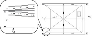 *1 12.5 mm *2 Left Edge of Paper *3 305.1 mm or more In the example above, the center line of the A1 register marks and the drawn line are aligned. Therefore, you do not need to adjust the image location. When you open the [Adjust Image Position] screen again after you close that screen by pressing [OK], the values on screen are returned to [0]. Nevertheless the adjusted value is effective. If you repeat steps, read off the value of register marks from new test page and input the new value.
|
Fine Adjusting the Zoom Ratio of the Image on a Custom Paper Type:
Select the paper type that you want to edit from the list → press [Details/Edit].
Press [Change] next to [Adjust Image Position].
Press [Output Test Page].
Select a paper source that contains a custom paper size → press [Start Printing].
The test page is printed. Check the zoom ratio of the image, and follow the procedure described below as necessary.
Set the zoom ratio.
If you enter the enlargement/reduction ratio (%):
1. Press [Fine Adjust Zoom] displayed on [Adjust Image Position].
2. Set the enlargement/reduction ratio (%) you want → press [OK].
|
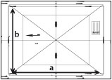
[a]:
|
Enlarges or reduces the image in the direction that is parallel to the feeding direction according to the inputted ratio.
|
|
[b]:
|
Enlarges or reduces the image in the direction that is perpendicular to the feeding direction according to the inputted ratio.
|
As necessary, try printing out the test page paper again and then check the correction amount.
If you enter the value of the test page paper you measured manually:
1. Measure the length of a and b on the test page paper manually.
2. Press [Fine Adjust Zoom] displayed on [Adjust Image Position].
3. Press [Enter Test Page Value].
4. Enter the length of the test page on both [Front Side] and [Back Side] → press [OK].
For example, if the measured length of [a] is 360.4 mm, enter 360.4. The difference in length (0.4 mm in this case), is automatically reduced, so that the image is printed in the correct size.
|
[a]:
|
Enter the measured length of the side that is parallel to the feeding direction.
|
|
[b]:
|
Enter the measured length of the side that is perpendicular to the feeding direction.
|
5. Press [OK].
As necessary, try printing the test page again and then check the correction amount.
Press [Close] → [OK].
|
IMPORTANT
|
|
139.7 mm x 182.0 mm to 330.2 mm x 487.7 mm paper can be used for the test pages. Make sure that a sufficient supply of paper is loaded into the machine before starting this procedure.
Printing performance may not be optimal if you use the Fine Adjustment Zoom mode.
|
|
NOTE
|
|
If you perform a test page using paper smaller than 287 mm x 393 mm, you will not be able to measure the length of a and b since the entire image cannot be printed on the paper. In this case, enter the expanding/reducing percentage to adjust the zoom ratio, instead of entering the actual length of a and b.
|
Deleting Custom Paper Types:
Select the paper type that you want to delete → press [Delete].
Press [Yes].
|
NOTE
|
|
You can only delete user-registered paper types.
|
3.
Press [OK].