Adjusting the Secondary Transfer Voltage
You can adjust the Secondary Transfer Voltage (the voltage that transfers toner to the paper) when image blurring occurs.
 |
Adjustments made in <Adjust Secondary Transfer Voltage> may affect the <Adjust Image Position> setting. Readjust <Adjust Image Position> as needed. |
Configuring/Printing the Chart
To adjust the secondary transfer voltage, first print the chart page.
1
Press <Change> in <Adjust Secondary Transfer Voltage>.
2
Select the secondary transfer voltage adjustment method.
Press <Do Not Use Scanner> to view the printed chart, identify the optimal patch, and make manual adjustments.
Press <Use Scanner> to scan the printed chart and have the optimal patch identified and adjustments made automatically.

If you selected <Use Scanner>, the usable paper sizes are A3, A4, 11" x 17", and LTR.
3
Press <Chart Print Settings>.
4
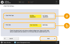
Specify the settings for the chart to be printed and press <Next>.

 <Chart Print Type>
Select <For Fine Adjustment> to make fine adjustments or <For Coarse Adjustment> if major adjustment is required.
If you selected <For Fine Adjustment>, a chart is printed with adjustments in increments of ±1.
If you selected <For Coarse Adjustment>, a chart is printed with adjustments in increments based on the status of the machine.
 <Print Side>
Select the side on which the secondary transfer voltage is to be adjusted.
 In any of the following situations, select <Front Side Only>. If <2nd Side of 2-Sided Page> is set to <On> for a custom paper. If you loaded paper in the multi-purpose tray and selected <2nd Side of 2-Sided Page> in <Paper Type>. | |
If you selected <2-Sided>, see Paper Available for 2-Sided Copying/2-Sided Printing for the papers that can be used for charts. |
5
Select the paper source in which the custom paper is loaded  press <OK>.
 press <OK>.
6
Press <Chart Print> or <Chart Print/Scan>.
If you selected <Use Scanner> in step 2, press <Start Printing>.
The chart is printed.
Adjusting the Secondary Transfer Voltage
Use the printed chart to adjust the secondary transfer voltage. The procedure differs depending on the secondary transfer voltage adjustment method selected in step 2 of "Configuring/Printing the Chart".
If you selected <Do Not Use Scanner>
Visually identify the optimal patch in the chart and adjust the secondary transfer voltage.
1
Check the optimal patch in the printed chart.
With the current settings, chart numbers are printed in magenta.

Check the chart as you sequentially increase from negative values to positive values. When you reach a point where the density within the patch appears uniform (-8 in the example), compare it with a patch with a value that is higher by 2 (-7 and -6 in the example) and select the value you consider to be optimal.

A side that has a single asterisk (*) printed next to the chart number is the front side.
Where there is no discernible difference among the selected numbers, choose the middle of the three values (-7 in the example).
2
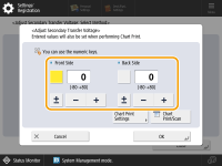
In the <Adjust Secondary Transfer Voltage> screen, enter the number confirmed in the chart.
Select <Front Side> or <Back Side> and enter the number using <-> or <+>.

 In either of the following situations, adjust the value for <Back Side>. If <2nd Side of 2-Sided Page> is set to <On> for a custom paper. If you loaded paper in the multi-purpose tray and selected <2nd Side of 2-Sided Page> in <Paper Type>. |
3
Press <OK>.
If you selected <Use Scanner>
Scan the chart on the scanner to have the optimal patch identified automatically.
1
Place the chart on the platen glass.
Place the chart while following the on-screen instructions.
2
Close the feeder and press <Start Scanning>.
The chart is scanned.
If the chart was printed on both sides of the paper, place the other side of the chart on the platen glass and press <Start Scanning> again.

You may not be able to scan special paper such as colored paper, transparencies, pre-punched paper, or labels. To scan special paper, select <Do Not Use Scanner> and make the adjustment manually.
3
Open the feeder and remove the chart.
4
Press <OK>.