Configuring Inspection Settings
Configure settings such as the inspection area and inspection level for each inspection job. Configure the inspection settings for all of the master images.
Inspection Area
The types of inspection areas are as follows. You can configure up to 64 inspection areas per page.
Area Type | Description |
[Excluded Areas] | Area where inspection is not performed |
[High Priority Inspection Areas] | Area configured with the strictest standards |
[Standard Inspection Areas] | Area configured with the regular standards |
[Low Priority Inspection Areas] | Area configured with the most permissive settings |
IMPORTANT |
If the multiple different types of areas overlap, the setting type that is uppermost in the above table takes precedence. Example: If [Excluded Areas] and [High Priority Inspection Areas] overlap, the overlapping area is not inspected. If [High Priority Inspection Areas] and [Standard Inspection Areas] overlap, the overlapping area is treated as [High Priority Inspection Areas]. Areas where an inspection area is not specified are not inspected. |
Procedure
If the [Inspection Settings] screen is displayed, start from Step 3.
1.
On the main screen, select the inspection job to be configured
2.
Display the [Inspection Settings] screen using any of the following methods
Click [Inspection Settings] from [File] in the menu bar.
Click [Inspection Settings] in the toolbar.
Right-click the selected inspection job and click [Inspection Settings].
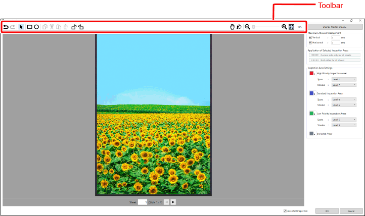
The [Inspection Settings] screen is displayed.
NOTE |
Tools for creating and editing inspection areas are displayed on the screen. Refer to the following for details. |
3.
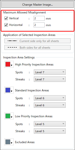
Set the misalignment tolerance
The misalignment tolerances of the output position of the image on the paper can be set in each of the vertical and horizontal directions. This setting applies to all of the pages.
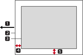
 Paper feeding direction
 Paper
Paper Image
Image [Vertical]
 [Horizontal]
[Vertical] | Input the misalignment tolerance in the paper feeding direction. The horizontal direction on the screen when the image scanned for the master image is not rotated is the paper feeding direction. |
[Horizontal] | Input the misalignment tolerance in the main scanning direction. The vertical direction on the screen when the image scanned for the master image is not rotated is the main scanning direction. |
IMPORTANT |
Check the orientation when the paper is ejected and set the misalignment tolerances correctly. If the image scanned for the master image is rotated by 90 degrees to the left or right on the screen, the specified length and width are the reverse of the length and width as seen on the screen. |
Select the check box for the misalignment directions to be inspected, and input the tolerances.
If the [Unit] is set to [Millimeters] on the [Preferences] screen
This can be specified in the range of 0.1 to 3.0 mm in 0.1 mm increments.
If the [Unit] is set to [Inches] on the [Preferences] screen
This can be specified in the range of 0.0039" to 0.1181" in 0.0001" increments.
4.
Set the inspection areas
Repeat the following procedure to set the areas to be inspected.
IMPORTANT |
If an inspection job for which no inspection area is configured is executed, images are not inspected. To inspect the entire page, specify an inspection area that covers the entire page. If the print job to be inspected contains numbers, text, and variable data that differ between the copies, set the areas where these are printed as [Excluded Areas]. |
In the toolbar, click  ([Insertion tool for inspection area (rectangle)]) or
  ([Insertion tool for inspection area (oval)]).
Select the type of inspection area from the drop-down menu.
Refer to the following for details on the types of inspection areas.
Drag the mouse pointer over the image to set the area.
NOTE |
You do not need to set areas for all of the types. You can change the colors of the frames around each inspection area. Select the color from the drop-down list on the left side of the inspection area name as needed. The selected color is not applied to other inspection jobs. |

5.
Check the overlap and settings of the inspection areas
Move the mouse pointer over  ([Inspection area confirmation]).
Each area becomes filled in with the corresponding frame color.
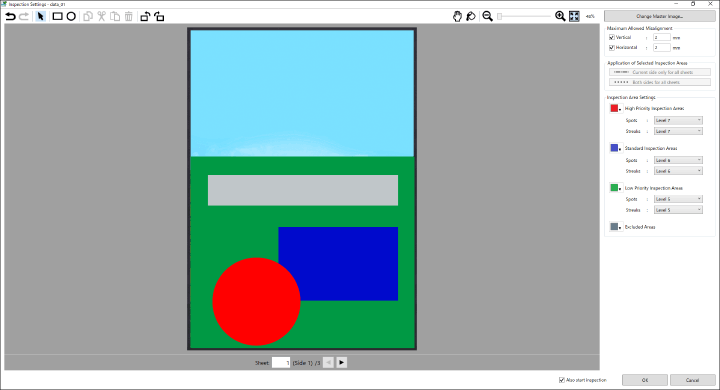
If the areas overlap, check whether that area has the intended settings.
Refer to the following for details on the order of precedence of the settings of overlapping areas.
Use the tools to set the areas again if needed.
Refer to the following for details on the toolbar icons.
6.
Specify the range of application of the inspection area
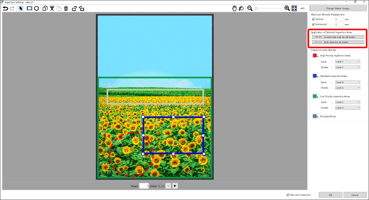
If you also want to apply the inspection areas that you configured with the procedure so far to other pages, specify the application destinations for each inspection area using the following procedure.
Select  ([Selection tool for inspection area]) and then select the target inspection area.
Specify the range of application in [Application of Selected Inspection Areas].
For areas to which [Both sides for all sheets] is applied, the line style of the frame line changes as follows. If the area is edited after this is specified, the edit results will be applied to all of the other pages.

For areas to which [Current side only for all sheets] is applied, the line style of the frame line changes as follows. If the area is edited after this is specified, the edit results will be applied to the same face of the other pages.

The line style of frame lines of inspection areas where neither is specified is as follows. If the area is edited after this is specified, it has no effect on the other pages or faces.

NOTE |
To return to per-page settings after selecting [Current side only for all sheets] or [Both sides for all sheets], click |
7.
Set the inspection areas in the images of the other pages
Click the  and
and  icons at the bottom of the screen to switch pages.
Set the inspection areas on each page.
Refer to Steps 4 to 6 for details.
IMPORTANT |
For areas that are enclosed by a line style other than a solid line, edit results are also applied to other pages or faces. Refer to Step 6 for the meanings of the line style of the frame. |
8.
Set the inspection levels of [Spots] and [Streaks] for each inspection area
IMPORTANT |
The inspection levels of the same type of inspection area on all of the pages are set to the levels specified here, regardless of the currently displayed page and the ranges of application of the areas that were set in Steps 6 and 7. If there are multiple inspection areas that are the same type in a single inspection job, different inspection levels cannot be set for each area. |
Specify the inspection level with the higher numerical value to have stricter inspection standards.
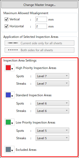
Specify the inspection level of [Standard Inspection Areas].
Select from among the range of [Level 8] to [Level 2].
Specify the inspection levels of [High Priority Inspection Areas] and [Low Priority Inspection Areas].
[High Priority Inspection Areas]
Only levels higher than [Standard Inspection Areas] can be specified in [High Priority Inspection Areas]. For example, if [Standard Inspection Areas] is set to [Level 6], then the range of inspection levels that can be specified in [High Priority Inspection Areas] is [Level 9] to [Level 7].
[Low Priority Inspection Areas]
Only levels lower than [Standard Inspection Areas] can be specified in [Low Priority Inspection Areas]. For example, if [Standard Inspection Areas] is set to [Level 6], then the range of inspection levels that can be specified in [Low Priority Inspection Areas] is [Level 5] to [Level 1].
9.
After you have finished the settings, click [OK]
If the [Also start inspection] check box is selected, the [Number of Copies to Inspect] screen is displayed. If the [Also start inspection] check box is not selected, the main screen is displayed.
Refer to the following for details on the procedure for executing an inspection.