Adjusting the Image Position
You can adjust the printed image position, which is misaligned or distorted, by confirming test pages and specifying setting values.
You can automatically adjust the image position by installing the "Sensing Unit-B."Adjusting the Image Position Automatically (Optional)
You can automatically adjust the image position by installing the "Sensing Unit-B."Adjusting the Image Position Automatically (Optional)
Outputting a Test Page
Print a test page when adjusting the position of images.
1
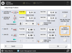
Press <Change> for <Adjust Image Position>.
When the Sensing Unit is not attached, proceed to step 3.
2
Press <Adjust Manually>.
3
Press <Output Test Page>.
4
Enter the number of test pages to make  press <Next>.
5
Select a paper source that contains a custom paper type press <Start Printing>.
A test page is printed.

For information on paper that can be used as test pages, see Paper Available for Two-Sided Printing.
Make sure that a sufficient supply of paper is loaded in the paper source before outputting the test pages.
Adjusting Lead Edge Alignment of the Image
This setting enables you to adjust the image position, by checking whether the register mark and the image at the leading edge toward the feeding direction are aligned on the test page.
1
Check the position of the lead edge image on the front side of the test page.
In the example below, adjustment is required because the center line of the register mark is 0.4 mm outside the edge of the test page. Follow the procedure described below to adjust the position of the lead edge image on the front side of the test page.
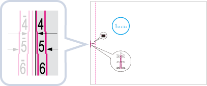
The test page with "1st side" printed on it is the front side.
2
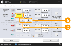
In the <Adjust Image Position> screen, enter the value confirmed on the test page that aligns the center line of the register mark with the edge of the paper.
In case of the example described above, set "+ 0.4" for <Front Side>.
Use <-> and <+> in <Front Side> in <Lead Edge (e) Alignment> to enter the value.
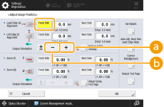
 <+>
<+>Press when the center line of the register mark is located outside the edge of the test page (the center line of the register mark is NOT printed). The image is shifted to the backwards as seen from the feeding direction of the paper, according to the entered value.
 <->
<->Press when the center line of the register mark is located inside of the edge of the test page. The image is shifted to the forwards as seen from the feeding direction of the paper, according to the entered value.
3
Turn over the test page check the lead edge image on the back side of the test page.
4
Enter the value confirmed on the test page that aligns the center line of the register mark with the edge of the paper.
Use <-> and <+> in <Back Side> in <Lead Edge (e) Alignment> to enter the value.
5
Print the test page again, and check the image position press <OK>.
Repeat the correction again, if necessary.

When you open the <Adjust Image Position> screen again after you close that screen by pressing <OK>, the values on screen are returned to <0>. However, the adjusted value is still effective. If you repeat steps, read off the value of register marks from new test page and input the new value.
To restore the accumulated value, press <Restore Initial Settings>.
6
Press <OK>.
Adjusting Left Edge Alignment of the Image
This setting enables you to adjust the image position, by checking whether the register marks on the test page align with the image at the left edge of the paper toward the feeding direction.
1
Check the position of the left edge image on the front side of the test page.
In the example below, adjustment is required because the center line of the register mark is 0.4 mm outside the edge of the test page. Follow the procedure described below to adjust the position of the lead edge image on the front side of the test page.
2
In the <Adjust Image Position> screen, enter the value confirmed on the test page that aligns the center line of the register mark with the edge of the paper.
In case of the example described above, set "+ 0.4" for <Front Side>.
Use <-> and <+> in <Front Side> in <Left Edge (i) Alignment> to enter the value.
 <+>
<+>Press when the center line of the register mark is located outside the edge of the test page (the center line of the register mark is NOT printed). The image is shifted to the right as seen from the feeding direction of the paper, according to the entered value.
<->Press when the center line of the register mark is located inside of the edge of the test page. The image is shifted to the left as seen from the feeding direction of the paper, according to the entered value.

If you print the test page using paper whose vertical side toward the feeding direction is 12" (304 mm) or more in length, the register mark on the left edge will not be printed properly. In this case, measure the length of <i> mark. If the measured length is shorter than 20 mm, enter the difference value with <+>, if the measured length is longer than 20 mm, enter the difference value with <->.
3
Turn over the test page check the left edge image on the back side of the test page.
4
Enter the value confirmed on the test page that aligns the center line of the register mark with the edge of the paper.
Use <-> and <+> in <Back Side> in <Left Edge (i) Alignment> to enter the value.
5
Perform the test page again, and check the image position press <OK>.
Repeat the correction again, if necessary.
When you open the <Adjust Image Position> screen again after you close that screen by pressing <OK>, the values on screen are returned to <0>. However, the adjusted value is still effective. If you repeat steps, read off the value of register marks from new test page and input the new value.
To restore the accumulated value, press <Restore Initial Settings>.
6
Press <OK>.
Adjusting the Zoom Ratio of the Image
Depending on the paper type, the heat generated by the fixing unit may cause the paper to expand or shrink slightly. In this case, images may also be enlarged or reduced accordingly. This function enables you to set the zoom ratio of the image for each paper, or enlarge the reduced image to match the zoom ratio of the image on the second side of the paper. You can adjust the zoom ratio of the image either by entering the enlargement/reduction ratio, or by entering the value of the test page you measured manually.
1
Check the images on the output test page.
2
Enlarge or reduce images on the <Adjust Image Position> screen.
 If you enter the enlargement/reduction ratio (%)
1 | Set the enlargement/reduction ratio (%) for <Zoom (f)> and <Zoom (d)> on <Adjust Image Position> screen 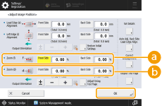 <Zoom (f)> <Zoom (f)>Enlarges or reduces the image in the direction that is parallel to the feeding direction according to the inputted ratio. <Zoom (d)>Enlarges or reduces the image in the direction that is perpendicular to the feeding direction according to the inputted ratio. As necessary, try printing out the test page paper again and then check the correction amount. |
If you enter the value of the test page you measured manually
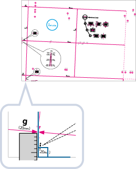
1 | Measure the length of the <f> and <d> marks on the test page manually. The default values are <f> = 360.0 mm and <d> = 250.0 mm. 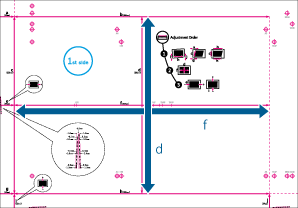 If you print the test page using paper smaller than 10 5/8" x 15" (270 mm x 380 mm), you cannot measure the length of <f> and <d> as the entire image will not be printed on the paper. In this case, calculate the expanding/reducing percentage by comparing the measured length of 'f/2' and 'd/2' with the default values (f/2: 180 mm, d/2: 125 mm). By using the calculated percentage, adjust the zoom ratio. |
2 | Press <Adjust Using Test Page>. |
3 | Enter the length of the test page on both front and back sides For example, if the measured length of <f> is 360.4 mm, enter 360.4. The difference in length (0.4 mm in this case), is automatically reduced, so that the image is printed in the correct size. 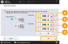 <f> <f>Enter the measured length of <f> mark on the test page. <d>Enter the measured length of <d> mark on the test page. As necessary, try printing the test page again and then check the correction amount. |
3
Press <OK>.
Correct Image Misalignment
This setting enables you to correct the misaligned image position by adjusting the margin on the left side of the paper to the feeding direction.
Right side | |||
 Feeding direction | Lead edge | 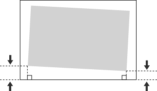 | Rear edge |
Left side |
 |
If the printed image is misaligned, make sure to specify the <Correct Image Misalignment> mode first. |
1
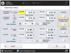
Press <Change> for <Adjust Image Position>.
2
Press <Set Details> <Correct Image Misalignment>.
If you want to enter the values of the test page you measured manually
If you want to enter the values of the test page you measured manually
1 | Measure the length of <i> and <j> on the test page. <i> is printed on the front left edge of the feeding direction, while <j> is printed on the rear left edge. 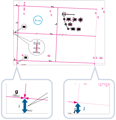 Example: <i> = 21.0 mm, and <j> = 20.5 mm Measure the length of the <i> and <j> marks correctly as shown below.
| ||||
2 | On the <Correct Image Misalignment> screen, enter the actual <i> and <j> values for the front and back sides 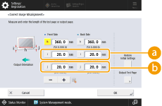 <i> <i>Enter the measured length of <i> mark on the test page. <j>Enter the measured length of <j> mark on the test page. Following the example, setting a length of 21.0 mm for <i> and 20.5 mm for <j> causes the skewed difference of 0.5 mm to be automatically corrected. | ||||
3 | Perform the test page again, and check the image position |
If you want to enter the values of the output paper you measured manually
1 | Check the image position on the output paper. 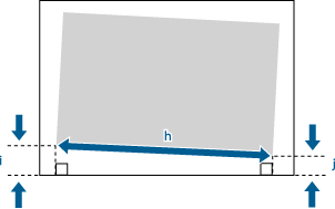 In this example, the length of <h> is 360.0 mm, <i> is 21.0 mm, and <j> is 20.5 mm. |
2 | Measure and enter values of the following items Using the following three numerical values, a device automatically adjusts so that printing area and a paper may become parallel. 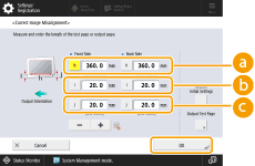 <h> <h>Enter the measured length of the left side on the printing area. <i>Enter the measured length from the left side lead edge of the printing area to the left side edge of the paper.  <j> <j>Enter the measured length from the left side tail end of the printing area to the left side edge of the paper. Following the example, setting a length of 360.0 mm for <h>, 21.0 mm for <i>, and 20.5 mm for <j> causes the alignment difference of 0.5 mm to be automatically corrected. |
3 | Output the print again, and check the image position Repeat the correction again, if necessary. |
3
Press <OK> <OK>.
|
To restore the accumulated value, press <Restore Initial Settings>. If register marks are printed on the output paper, the printed area is equal to the area inside the register marks. |
Correct Distortion (Trapezoid)
This setting enables you to correct the image shape by equalizing the length of the right and left side of the printing area when the image is printed like a trapezoid.
Right side | |||
Feeding direction | Lead edge | 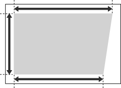 | Rear edge |
Left side |
|
Make sure to specify the <Correct Image Misalignment> mode and then the <Corr. Distortion (Trapezoid)> mode, before specifying the <Corr. Distortion (Parallelogram)> mode. |
1
Press <Change> for <Adjust Image Position>.
2
Press <Set Details> <Corr. Distortion (Trapezoid)>.
If you want to enter the values of the test page you measured manually
1 | Measure the length of the <b> and <h> marks on the test page. The mark <b> is printed on the right side and the mark <h> is printed on the left side of the feeding direction. 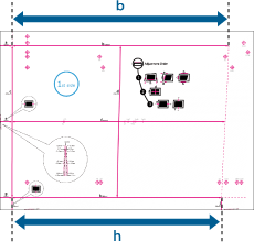 In this example, the length of <b> is 360.0 mm, and <h> is 355.5 mm. |
2 | On the <Corr. Distortion (Trapezoid)> screen, enter "250.0" for <c> for both the front and back sides. 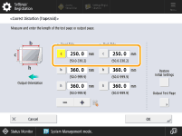 |
3 | Enter the <b> and <h> values for front and back sides. 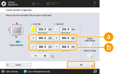 <b> <b>Enter the measured length of <b> mark on the test page. <h>Enter the measured length of <h> mark on the test page. Following the example, setting a length of 360.0 mm for <b> and 355.5 mm for <h> causes the distortion difference of 0.5 mm to be automatically corrected |
4 | Perform the test page again, and check the image position Repeat the correction again, if necessary. |
If you want to enter the values of the output paper you measured manually
1 | Check the image position on the output paper. 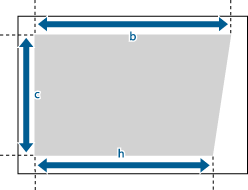 In this example, the length of <c> is 250.0 mm, <b> is 360.0 mm, and <h> is 355.5 mm. |
2 | Measure and enter values of the following items Using the following three numerical values, a device automatically adjusts so that the distorted printing area may be corrected.  <c> <c>Enter the measured length of the lead edge of the printing area in relation to the feeding direction. <b>Enter the measured length from the right side lead edge of the printing area to the right side tail end of the printing area. <h>Enter the measured length from the left side lead edge of the printing area to the left side tail end of the printing area. Following the example, setting a length of 250.0 mm for <c>, 360.0 mm for <b>, and 355.5 mm for <h> causes the alignment difference of 0.5 mm to be automatically corrected. |
3 | Output the print again, and check the image position Repeat the correction again, if necessary. |
3
Press <OK> <OK>.
|
To restore the accumulated value, press <Restore Initial Settings>. If register marks are printed on the output paper, the printed area is equal to the area inside the register marks. |
Correct Distortion (Parallelogram)
This setting enables you to correct the image shape by equalizing the length from the <a> and <g> to the lead edge of the paper when the image is printed like a parallelogram.
Right side | |||
Feeding direction | Lead edge | 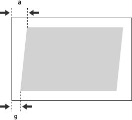 | Rear edge |
Left side |
|
Make sure to specify the <Correct Image Misalignment> mode first, before specifying the <Corr. Distortion (Parallelogram)> mode. |
1
Press <Change> for <Adjust Image Position>.
2
Press <Set Details> <Corr. Distortion (Parallelogram)>.
If you want to enter the values of the test page you measured manually
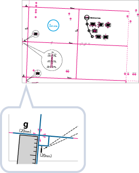
1 | Measure the length of the <g> and <a> marks on the test page. The mark <g> is printed on the left side lead edge, and the mark <a> is printed on the right side lead edge of the feeding direction. 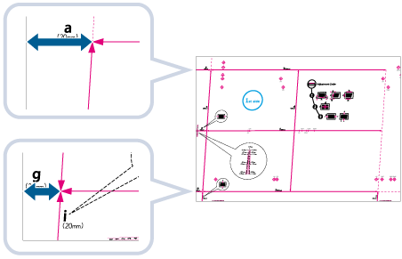 In this example, the length of <g> is 20.5 mm, and <a> is 21.0 mm. Measure the length of the <g> and <a> marks correctly as shown below. 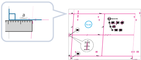 |
2 | On the <Corr. Distortion (Parallelogram)> screen, enter "250.0" for <c> for both the front and back sides. |
3 | Enter the <g> and <a> values for Front Side and Back Side 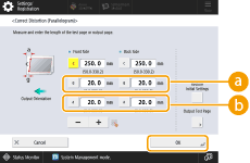 <g> <g>Enter the measured length of <g> mark on the test page. <a>Enter the measured length of <a> mark on the test page. Following the example, enter 20.5 for <g> and 21.0 for <a>. The difference between <g> and <a> (0.5 mm) is automatically corrected. |
If you want to enter the values of the output paper you measured manually
1 | Check the image position on the output paper. 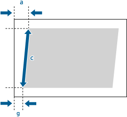 In this example, the length of <c> is 250.0 mm, <g> is 20.5 mm, and <a> is 21.0 mm. |
2 | Measure and enter values of the following items Using the following three numerical values, a device automatically adjusts so that printing area and a paper may become parallel.  <c> <c>Enter the measured length of the lead edge of the printing area in relation to the feeding direction. <g>Enter the measured length from the left side lead edge of the printing area to the lead edge of the output paper. <a> Enter the measured length from the right side lead edge of the printing area to the lead edge of the output paper. Following the example, enter 250.0 for <c>, 20.5 for <g>, and 21.0 for <a>. The difference between <g> and <a> (0.5 mm) is automatically corrected. |
3 | Perform the test page again, and check the image position Repeat the correction again, if necessary. |
3
Press <OK> <OK>.
|
To restore the accumulated value, press <Restore Initial Settings> If register marks are printed on the output paper, the printed area is equal to the area inside the register marks. |
Correct Misalignment
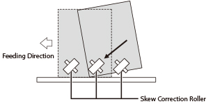
If the printed image is slanted on the particular paper (such as thin paper) only, this feature may enable you to adjust the transferring position of the paper.
The skew correction roller is located in the feeding unit of the marking engine. It adjusts the registered position of fed paper by pushing the paper diagonally against the wall inside the feeding unit. If the setting of skew correction level is incorrect, the printed image is slanted.
1
Check the front side and back side of the test page.
You can check whether the printed image is skewed, by comparing the length from "i" and "j" register marks to the left side edge of paper to the feeding direction.
2
Press <Correct Misalignment> on the <Adjust Image Position> screen.
3
Press <Front Side> or <Back Side> of the desired item (<Conveyance Power: Front>, <Conveyance Power: Rear>, <Conveyance Speed: Rear>), then perform the adjustment by pressing <+> or <-> press <OK>.
You can make adjustment for standard size paper and long sheet paper.
<Conveyance Power: Rear> and <Conveyance Speed: Rear> are valid only when adjusting long sheet paper.
Adjustment for <Conveyance Power: Front>:
To increase the pressure and speed of the skew correction roller to push the paper, as shown below, press <+>. Setting the value with too high and too low may cause a paper jam. And if you set the value with too low, the image on the paper such as thin paper may be slanted.
Adjustment for <Conveyance Power: Rear>:
If the image alignment varies greatly for thick sheets, press <+>. If a paper jam occurs for thin sheets, press <->. If the condition is not improved, adjust the setting value in <Conveyance Speed: Rear> bellow.
Adjustment for <Conveyance Speed: Rear>:
If the image alignment varies greatly for thick sheets, press <+>. If a paper jam occurs for thin sheets, press <->. (Make this adjustment if the condition is not improved even though you made the <Conveyance Power: Rear> adjustment.)
When printing on the first side (front side), white streaks, which are vertical to the feeding direction, appear about 30 mm from the bottom edge of the paper, decrease the setting value of the back side for<Correct Misalignment>. If the streaks appear even after the adjustment, increase the value for <Gloss> in <Adjust Gloss/Fine Black>. For more information on adjusting <Gloss>, see Adjust Gloss/Fine Black.
4
Press <OK>.
Print a test page again and check the image position as needed. If you need to make a further adjustment, repeat steps above.
Automatically Correcting the Back Side Lead Edge Alignment of the Image
In this feature, the paper length is measured. Based on the measured paper length, the position of the image on the second side is adjusted to match the position of the image on the first side. However, setting this feature to 'Off' may result in a more accurate registration for some paper types.
Setting Back Side Lead Edge Alignment Correction to 'On' results in a more accurate registration for the following paper types:
Paper with expansion and contraction after printing
Paper with the different width and length
Setting Back Side Lead Edge Alignment Correction to 'Off' results in a more accurate registration for the following paper type:
Paper with the same width and length
1
Press <Auto Adj. Back Side Lead Edge Align.> on the <Adjust Image Position> screen.
2
Press <On> or <Off> press <OK>.
Details of each item are shown below:
[On]: | The paper length is accurately measured for two-sided printing. The measured value is then calculated to adjust the position of the image on the second side. |
[Off]: | The paper length is not measured for two-sided printing. The value set for the Lead Edge Alignment Adjustment mode is used directly to adjust the image position. |
|
If you switch between [On] and [Off], check the image position set for the back side of the Lead Edge Alignment Adjustment mode again. |