Installation Location
Selecting and Configuring an Installation Location
Installation Location
Avoid installing the machine in the following locations.
Locations where a considerable amount of dust accumulates.
Locations near volatile or flammable materials, such as alcohol or paint thinner.
Locations where the machine is exposed to rapid changes in temperature.
If the room in which the machine is installed is cold but rapidly heated, water droplets (condensation) may form inside the machine. This may result in a noticeable degradation in the quality of the copied image, the inability to properly scan an original, or the copies having no printed image at all.
Locations near computers or other precision electronic equipment.
Electrical interference and vibrations generated by the machine during printing can adversely affect the operation of such equipment.
Locations near televisions, radios, or similar electronic equipment.
The machine might interfere with sound and picture signal reception. Insert the power plug into a dedicated power outlet, and maintain as much space as possible between the machine and other electronic equipment.
Locations near ultrasonic humidifiers or sprinkler humidifiers.
Be careful with the installation layout and operating environment when installing the machine in the following locations.
Locations near equipment (*) which releases volatile substances.
Volatile substances may get inside the machine and affect the image quality.
If you are using such equipment, consult your local authorized Canon dealer or service representative before use.
If you are using such equipment, consult your local authorized Canon dealer or service representative before use.
*Example: equipment which uses hot melt adhesives (bookbinding machines or laminators), aroma equipment, diazo copying machines etc.
Installing multiple machines
If you install multiple machines nearby, consult your local authorized Canon dealer or service representative about the installation layout before the installation so that the air intake section of a machine does not approach the exhaust section of other machines.
Do not remove the leveling feet.
Do not remove the leveling feet after the machine has been installed.
If you put weight on the front of the machine while the drawers, paper decks, or units within the machine are pulled out, the machine may fall forward. To prevent this from happening, make sure that the leveling feet are in place.
If you put weight on the front of the machine while the drawers, paper decks, or units within the machine are pulled out, the machine may fall forward. To prevent this from happening, make sure that the leveling feet are in place.
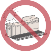
Direct Sunlight
Avoid installing the machine in direct sunlight.
If this is unavoidable, use curtains to shade the machine. Be sure that the curtains do not block the machine's ventilation slots or louvers, or interfere with the electrical cord or power supply.
If this is unavoidable, use curtains to shade the machine. Be sure that the curtains do not block the machine's ventilation slots or louvers, or interfere with the electrical cord or power supply.
Lighting
We recommend installing the machine in a location with at least 500 lux (75 cm above the floor) for normal operation and maintenance.
Delivery Pathway
The dimensions of the imagePRESS V1350 Marking Engine are 1,391 mm (W) x 1,130 mm (D) x 1,456 mm (H). Also, the weight of the Marking Engine is approximately 700 kg.
With these dimensions and weight in mind, check to make sure that there is enough moving space and required floor strength to deliver the machine.
With these dimensions and weight in mind, check to make sure that there is enough moving space and required floor strength to deliver the machine.
Floor Structure
Floor Structure
The floor on which this machine will be installed must have a floor load of at least 560 kg/m2. Even if the floor does not have this level of floor load, the machine can be installed near a pillar or beam. Consult with your building contractor before installing the machine.
The weight of the machine will be primarily focused on the floor through the adjuster and wheels. We recommend the use of a mat to distribute the weight.
We also recommend the use of a mat when installing the machine on carpet or wood flooring. For information about mats, contact your dealer.
Do not install the machine on an unstable floor or platform.
Standard Values of Floor Structure
Be sure to install the imagePRESS V1350 and optional equipment on the floor which satisfies the following standard.
Floor Stiffness | The amount of sinking in the floor must be 4 mm or less, if the load of 1,200 kg/m2 is applied to it. If this is not satisfied, use the floor plates partially. * Use the floor plates if the machine is installed on the mat, wooden floor, or rubber floor. * Depending on the amount of sinking in the floor, stack the floor plates to reduce the inequality of height of the joints. |
Floor Flatness | The flatness in arbitrary rectangular area 1,100 mm x 530 mm must be 4 mm or less. |
Floor Vertical Interval | The vertical interval between arbitrary two points of 1,000 mm interval must be 3 mm or less. (The amount of sinking in the floor is not included.) |
Floor Inclination | The inclination between arbitrary two points of 1,600 mm interval must be 3 mm or less. |
Measuring Methods for Each Standard Value
The standard values are measured according to the following procedures.
Use the iron plate as a floor plate, which corresponds to 890 mm x 487.5 mm in size, 13 kg in weight, and 4 mm in thickness.
Use the iron plate as a floor plate, which corresponds to 890 mm x 487.5 mm in size, 13 kg in weight, and 4 mm in thickness.
Floor Withstand Load | Confirm the specifications of the floor withstand load to the contractor of the building where the machine is scheduled to be installed. | ||
Floor Stiffness | Prepare one floor plate and put it on the place where the machine is scheduled to be installed. Measure the amount of sinking in the floor when two adults (approximately 150 kg) step onto the plate. From this measurements, estimate the amount of sinking in the floor when the machine is installed by doing proportional calculation. 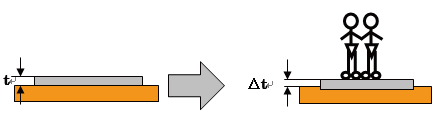 Calculation MethodEach parameter is specified as follows: t: the height from the floor to the upper surface of the floor plate Δt: the height from the floor to the upper surface of the floor plate when the load is applied Ts (mm/kgf): the constant of the estimated amount of sinking in the floor Ts (ME): the amount of sinking in the floor where this machine is installed First of all, calculate the constant of the estimated amount of sinking in the floor. Ts (mm/kgf) = (t - Δt)/150 Using this constant, estimate the amount of sinking in the floor where this machine is installed. Ts (ME) = (700 (kgf)/2) x Ts (mm/kgf) ExampleIn the case of t = 4 mm Δt = 3 mm The constant of estimated amount of sinking in the floor is calculated as shown below. (4 - 3)/150 = 0.006 In this example, the estimated amount of sinking in the floor where this machine is installed is 2.1 mm with the following formula. Ts (ME) = (700 (kgf)/2) x 0.006 = 2.1 | ||
Floor Flatness | Put one floor plate on the floor where the machine is scheduled to be installed, and put the simplified level on the center of it. To make the floor plate horizontal, insert some spacers (coins) under A or B of the floor plate, as shown in the illustration below. Calculate the floor flatness from the spacer's thickness and the number of them. 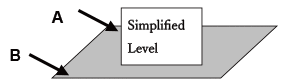 Calculation MethodUse coins which have same thickness as a spacer. Each parameter is specified as follows: t (mm): the thickness of the spacer a: the number of the spacers inserted under A b: the number of the spacers inserted under B When a > b, the floor flatness is calculated by the following formula. t x a (mm) ExampleThe coins of 1 mm in thickness are used as a spacer. If two spacers are inserted under A, and nothing is inserted under B to make the floor plate horizontal, the floor flatness is 2 mm. | ||
Floor Vertical Interval (This method is used when there is a step in the floor.) | Arrange two floor plates next to each other and put them on the floor where the machine is scheduled to be installed. According to the measuring method of the "Floor Flatness", set one floor plate horizontally. And then, set another one horizontally in the same way. Measure the difference of height between two floor plates.
| ||
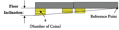
Floor Inclination (This method is used when the floor inclines gently.) | Arrange two floor plates next to each other and put them on the floor where the machine is scheduled to be installed. According to the measuring method of the "Floor Flatness", set one floor plate horizontally. And then, insert the spacers (coins) under another floor plate to set plate horizontally with its height same as the one that you have set first. In this case, insert the spacers at the arbitrary position of the floor plate edge. Measure the floor inclination with the thickness of the spacers that are located most away from the reference point (the point determined as a bench mark of the height). (See the illustration below.)
Calculation MethodUse coins which have same thickness as a spacer. Each parameter is specified as follows. t (mm): the thickness of the spacer a: the number of the spacers The floor flatness is calculated by the following formula. S = t x a (mm) ExampleThe coins of 1 mm in thickness are used as a spacer. If three spacers are inserted under the position that is most away from the reference point, the floor inclination is 3 mm (= 1 mm x 3). |

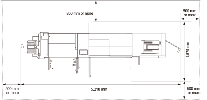
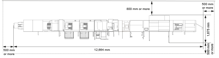
Installation Space
Necessary Installation Space
Keep the back of the machine at least 800 mm away from a wall.
Also, the space of 5 mm between each equipment is necessary to connect them.
Standard (minimum) configuration
imagePRESS V1350 + Booklet Finisher-AF + POD Deck-E
Full option (maximum) configuration
imagePRESS V1350 + Two-Knife Booklet Trimmer-B + Booklet Trimmer-G + Booklet Finisher-AF + Paper Folding Unit-K + High Capacity Stacker-J x 2 + Perfect Binder-F + Multi Function Professional Puncher-C + Document Insertion Unit-R + Inspection Unit-C + Sensing Unit-B + POD Deck-E + Secondary POD Deck-E
Minimum Space Required for Turning
The following is the minimum width required for turning the imagePRESS V1350 and each equipment at the corner of a corridor.
Dimension when Transporting (Width x Length) | Minimum Corridor Width Required* | |
imagePRESS V1350 (Marking Engine) | 1,391 mm x 1,130 mm | 2,293 mm |
imagePRESS V1350 (Fixing Station) | 936 mm x 775 mm | 1,716 mm |
imagePRESS V1350 (Buffer Pass Station) | 366 mm x 775 mm | 1,358 mm |
POD Deck-E | 982 mm x 792 mm | 1,762 mm |
Secondary POD Deck-E | 745 mm x 792 mm | 1,587 mm |
Sensing Unit-B | 750 mm x 515 mm | 1,410 mm |
Inspection Unit-B | 450 mm x 792 mm | 1,411 mm |
Inspection Unit-C | 750 mm x 515 mm | 1,410 mm |
Document Insertion Unit-R | 823 mm x 793 mm | 1,643 mm |
Static Eliminator-A | 450 mm x 792 mm | 1,411 mm |
Multi Function Professional Puncher-C | 445 mm x 795 mm | 1,411 mm |
High Capacity Stacker-J | 899 mm x 745 mm | 1,668 mm |
Paper Folding Unit-K | 502 mm x 793 mm | 1,439 mm |
Staple Finisher-AF | 800 mm x 792 mm | 1,626 mm |
Booklet Finisher-AF | 800 mm x 792 mm | 1,626 mm |
Booklet Trimmer-G | 1,835 mm x 790 mm | 2,498 mm |
Two-Knife Booklet Trimmer-B | 536 mm x 770 mm | 1,439 mm |
* Minimum width required for turning is the diagonal length of the machine (equipment) + about 500 mm.
Size and Weight of Each Component
Dimensions (W x D x H) | Weight | |
imagePRESS V1350 (Marking Engine, Fixing Station, Buffer Pass Station, and Power Supply Unit) | 2,691 mm x 1,165 mm x 1,456 mm | Approx. 1,065 kg |
POD Deck-E | 982 mm x 792 mm x 1,095 mm | Approx. 250 kg |
POD Deck-E + Secondary POD Deck-E | 1,794 mm x 792 mm x 1,095 mm | Approx. 482 kg |
Sensing Unit-B | 515 mm x 750 mm x 1,228 mm | Approx. 100.5 kg |
Inspection Unit-B | 250 mm x 792 mm x 1,040 mm | Approx. 49.5 kg |
Inspection Unit-C | 515 mm x 842 mm x 1,080 mm | Approx. 84.9 kg |
Document Insertion Unit-R | 746 mm x 793 mm x 1,407 mm | Approx. 61 kg |
Static Eliminator-A | 250 mm x 792 mm x 1,040 mm | Approx. 50 kg |
Multi Function Professional Puncher-C | 445 mm x 795 mm x 1,040 mm | Approx. 102 kg |
High Capacity Stacker-J | 899 mm x 745 mm (1,250 mm*) x 1,141 mm (To the top of the top tray) * When the eject tray is moved out of the stacker. | Approx. 120 kg |
High Capacity Stacker-J x 2 | 1,803 mm x 745 mm (1,250 mm*) x 1,141 mm (To the top of the top tray) * When the eject tray is moved out of the stacker. | Approx. 240 kg |
Paper Folding Unit-K | 336 mm x 793 mm x 1,190 mm | Approx. 71 kg |
Staple Finisher-AF | 800 mm x 792 mm x 1,239 mm | Approx. 133 kg (Including inner Puncher) |
Booklet Finisher-AF | 800 mm x 792 mm x 1,239 mm | Approx. 183 kg (Including inner Puncher) |
Booklet Trimmer-G | 2,095 mm x 790 mm x 1,040 mm (Including conveyer and output tray) | Approx. 178 kg (Including conveyer and output tray) |
Two-Knife Booklet Trimmer-B | 536 mm x 770 mm x 1,040 mm (Not including conveyer and output tray) | Approx. 145 kg (Not including conveyer and output tray) |
Installation Environment
 |
Blocking the machine's ventilation slots or louvers may adversely affect the quality of the image. Do not block the ventilation slots or louvers. |
Temperature and Humidity Conditions
Do not install the machine in locations with high or low heat and humidity, such as places with a water faucet, water heater, humidifier, air conditioner, heater, or a stove.
During operation, the permissible humidity range is 15 to 60% (with a room temperature of 20 to 27˚C).
There is a risk that the paper feed and image quality may be affected if the machine is used in a location that does not satisfy these specifications.
Temperature Gradient
Using an air conditioner during the winter or sudden temperature changes may have an adverse affect on image positioning, as this may cause the paper to bend or contract, and cause a malfunction of the machine due to condensation. In order to avoid these issues, control the temperature gradient so that it does not exceed 10˚C/H.
Ventilation
Ensure that there is an air exchange rate of at least 2 times/h and at least 110 m3 of space in the location where the machine will be installed.
This machine generates a slight amount of ozone etc. during normal use. Although sensitivity to ozone etc. may vary, this amount is not harmful. Ozone etc. may be more noticeable during extended use or long production runs, especially in poorly ventilated rooms. It is recommended that the room be appropriately ventilated, sufficient to maintain a comfortable working environment, in areas of machine operation.
Elevation Limitations
Install this machine at an elevation of 4,000 m or less.
*Atmospheric pressure at 4,000 m: 607.8 hPa (reference value)
*Atmospheric pressure at 4,000 m: 607.8 hPa (reference value)
Power Supply
Power Supply Conditions
Use these components within the power supply specifications listed below.
The power supply for components not listed in the table is supplied by the imagePRESS V1350 or other components.
Power Supply | Power Supply Cord/ Plug Specifications | The Length of the Power Cord | |
imagePRESS V1350 (Marking Engine) | 3 Phase 380-415 V AC, 50/60 Hz, 13.5 A | C532P6S/HUBBELL 4P5W | 3 m |
POD Deck-E | 220-240 V AC, 50/60 Hz, 5.0 A | IEC 60884-1, VDE 0620 UK :BS 1363 Oceania: AS/NZS 3112 | 2 m |
Secondary POD Deck-E | 220-240 V AC, 50/60 Hz, 5.0 A | IEC 60884-1, VDE 0620 UK :BS 1363 Oceania: AS/NZS 3112 | 2 m |
Sensing Unit-B | 100-240 V AC, 50/60 Hz, 2.5 A | CEE 7/7 | 1.9 m |
Inspection Unit-B | 100-240 V AC, 50/60 Hz, 1.4 A | CEE 7/7 | 1.9 m |
Inspection Unit-C | 100-240 V AC, 50/60 Hz, 2.5 A | CEE 7/7 | 1.9 m |
Document Insertion Unit-R | 100-240 V AC, 50/60 Hz, 1.0 A | CEE 7/7 | 2 m |
Static Eliminator-A | 100-240 V AC, 50/60 Hz, 1.0 A | CEE 7/7 | 1.9 m |
Multi Function Professional Puncher-C | 230V AC, 50 Hz, 2.0 A | CEE 7/7 | 2.4 m |
High Capacity Stacker-J | 90-264 V AC, 47-63 Hz, 10 A | CEE 7/7 | 4.2 m |
Paper Folding Unit-K | From the finisher | From the finisher | - |
Staple Finisher-AF | 220-240 V AC, 50/60 Hz, 8.0 A | CEE 7/7 | 2 m |
Booklet Finisher-AF | 220-240 V AC, 50/60 Hz, 8.0 A | CEE 7/7 | 2 m |
Booklet Trimmer-G | From the finisher | From the finisher | - |
Two-Knife Booklet Trimmer-B | 220-240 V AC, 60 Hz, 2.3 A | CEE 7/7 | 2 m |
Maximum Energy Consumption
The maximum energy consumption of the imagePRESS V1350 and other components is listed below.
Maximum Energy Consumption | |
imagePRESS V1350 (Marking Engine) | 10,000 W *Including all options powered by main unit. |
POD Deck-E | 1,000 W |
Secondary POD Deck-E | 1,000 W |
Sensing Unit-B | 500 W |
Inspection Unit-B | 700 W |
Inspection Unit-C | 500 W |
Document Insertion Unit-R | 120 W or less |
Static Eliminator-A | 100 W or less |
Multi Function Professional Puncher-C | 480 W |
High Capacity Stacker-J | 220 W |
Paper Folding Unit-K | Included in the finisher |
Staple Finisher-AF | 500 W or less |
Booklet Finisher-AF | 500 W or less |
Booklet Trimmer-G | 300 W |
Two-Knife Booklet Trimmer-B | 440 W |