Installation Location
Selection/Structure of Installation Location
Direct Sunlight
Avoid installing the press in a location exposed to direct sunlight. If this is not possible, shade the press with curtains or a shading sheet. When using curtains, make sure that they do not block the ventilation slots of the press or cover the power cord or power plug.
Lighting
We recommend installing the press in a location with at least 500 lux (750 mm (29 1/2") above the floor) for normal operation and maintenance.
Transport Pathway
The dimensions of the PM (Print Module) of the varioPRINT iX1700 are 1,380 mm (54 3/8") (W) x 1,125 mm (44 1/4") (D) x 1,945 mm (76 5/8") (H). Also, the weight of the PM is approximately 1,040 kg (2292.8 lb). With the dimensions and weight of the PM in mind, check to make sure that there is enough moving space and required floor strength to transport the press.
Floor Structure
Floor Structure
The floor on which the press will be installed must have a floor load capacity of at least 450 kg/m2 (92.2 lb/ft2). If the floor does not have this capacity, consider installing the press near a pillar or beam. If the floor does not meet the load requirements, use load-distributing floor plates to ensure proper installation, upon consulting with your building contractor.
Additionally, the weight load of the press will be concentrated on the leveling feet and wheels, putting significant pressure on the floor (equivalent to 1,000 kg/m2 (204.8 lb/ft2) at most). To distribute this weight more evenly, we recommend using a floor plate if the floor has insufficient strength. Avoid installing the press on a soft floor, such as a floor covered in carpet or a wooden floor. (The press may be able to be installed on such floors by using a floor plate. For information about floor plates, contact your dealer.)
Additionally, the weight load of the press will be concentrated on the leveling feet and wheels, putting significant pressure on the floor (equivalent to 1,000 kg/m2 (204.8 lb/ft2) at most). To distribute this weight more evenly, we recommend using a floor plate if the floor has insufficient strength. Avoid installing the press on a soft floor, such as a floor covered in carpet or a wooden floor. (The press may be able to be installed on such floors by using a floor plate. For information about floor plates, contact your dealer.)
Do not install the press on an unstable floor or platform.
Floor Property Requirements
Ensure that the varioPRINT iX1700 and optional equipment are installed on a floor that meets the following requirements:
Floor Stiffness | The floor deflection must not exceed 4 mm (0.16") when a load of 1,000 kg/m2 (204.8 lb/ft2) is applied. |
Floor Flatness | The flatness in an arbitrary rectangular area (1,400 mm x 800 mm (55 1/8" x 31 1/2")) must not exceed 4 mm (0.16"). |
Floor Height Difference | The height difference between any two points on the floor that are 1,000 mm (39 3/8") apart must not exceed 3 mm (0.12"). (Floor deflection is not included.) |
Floor Inclination | The inclination between any two points on the floor that are 1,600 mm (63") apart must not exceed 3 mm (0.12"). |
Calculating Floor Properties
Use a laser level to measure the relative height of the adjuster ground contact points for all modules (four points for each module).
Use the relative height of the adjuster on the front left of the PM (Print Module) as the reference point, and confirm that the relative heights of the other adjuster ground contact points are within ±5 mm (0.2") of that reference point.
Installation Space
Necessary Installation Space
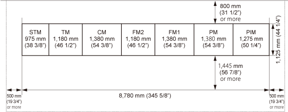
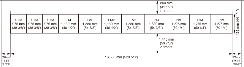
The following space is required for maintenance purposes.
Between the rear of the press and the wall: 800 mm (31 1/2") or more
Between the floor and the ceiling: 2,645 mm (104 1/8") or more
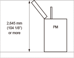
Also keep in mind that a 5 mm (0.2") gap is required at the connection points of each module.
* The dimensions of the standard and full configurations given below include a 5mm (0.2") gap between each module.
Standard (minimum) configuration
With one unit of STM (Stacking Module) and one unit of PIM (Paper Input Module)
Full Configuration
With three units of STM (Stacking Module) and three units of PIM (Paper Input Module)
Minimum Space Required for Turning
The following is the minimum width required for turning each module at the corner of a corridor.
Module | Dimensions when Transporting (W x D) | Minimum Corridor Width Required* |
PM (Print Module) | 1,380 mm x 1,125 mm (54 3/8" x 44 1/4") | 2,280 mm (89 3/4") |
PIM (Paper Input Module) | 1,275 mm x 870 mm (50 1/4" x 34 1/4") | 2,044 mm (80 1/2") |
FM1 (Fixation Module 1) | 1,380 mm x 870 mm (54 3/8" x 34 1/4") | 2,131 mm (83 7/8") |
FM2 (Fixation Module 2) | 1,180 mm x 870 mm (46 1/2" x 34 1/4") | 1,966 mm (77 3/8") |
CM (Cooling Module) | 1,380 mm x 870 mm (54 3/8" x 34 1/4") | 2,131 mm (83 7/8") |
TM (Turning Module) | 1,180 mm x 870 mm (46 1/2" x 34 1/4") | 1,966 mm (77 3/8") |
STM (Stacking Module) | 975 mm x 870 mm (38 3/8" x 34 1/4") | 1,807 mm (71 1/8") |
* The minimum width required for turning is the diagonal length of the module + about 500 mm (19 3/4").
Size and Weight of Each Module
Module | W x D x H | Weight |
PM (Print Module) | 1,380 mm x 1,125 mm x 2,335 mm (54 3/8" x 44 1/4" x 92")*1 | Approx. 1,040 kg (2292.8 lb)*2 |
PIM (Paper Input Module) | 1,275 mm x 1,065 mm x 1,260 mm (50 1/4" x 42" x 49 5/8")*3 | Approx. 620 kg (1366.9 lb) |
FM1 (Fixation Module 1) | 1,380 mm x 1,065 mm x 1,260 mm (54 3/8" x 42" x 49 5/8") | Approx. 650 kg (1433 lb) |
FM2 (Fixation Module 2) | 1,180 mm x 1,065 mm x 1,260 mm (46 1/2" x 42" x 49 5/8") | Approx. 520 kg (1146.4 lb) |
CM (Cooling Module) | 1,380 mm x 870 mm x 1,260 mm (54 3/8" x 34 1/4" x 49 5/8") | Approx. 460 kg (1014.1 lb) |
TM (Turning Module) | 1,180 mm x 870 mm x 1,260 mm (46 1/2" x 34 1/4" x 49 5/8")*3 | Approx. 390 kg (859.8 lb) |
STM (Stacking Module) | 975 mm x 870 mm x 1,150 mm (38 3/8" x 34 1/4" x 45 1/4") | Approx. 290 kg (639.3 lb) |
*1 Height including attention light. Height to PM top surface: 1,910 mm (75 1/4")
*2 Including ink/conditioning liquid/maintenance liquid pack
*3 Height including output area: 1,340 mm (52 3/4")
Printing Environment
IMPORTANT
Blocking the ventilation slots or louvers of the press may adversely affect the quality of the image. Do not block the ventilation slots or louvers.
Temperature and Humidity Conditions
Do not install the press in locations with high or low heat and humidity, such as places with a water faucet, water heater, humidifier, air conditioner, heater, or stove.
During operation, the permissible humidity range is 30% to 60% (with a room temperature of 20˚C to 27˚C (68˚F to 80.6˚F)).
There is a risk that the media transportation and image quality may be affected if the press is used in a location that does not satisfy these specifications.
The permissible humidity range for media storage is 30% to 60% (with a room temperature of 20˚C to 27˚C (68˚F to 80.6˚F)). Storing media in a location that does not meet these specifications may affect the media transportation and image quality.
Temperature Gradient
Using an air conditioner during the winter or sudden temperature changes may have an adverse effect on image positioning, as this may cause the media to bend or contract, and cause a malfunction of the press due to condensation. In order to avoid these issues, control the temperature gradient so that it does not exceed 10˚C (50˚F)/H.
Ventilation
Ensure that there is an air change rate of at least three times/h and at least 120 m3 (4,237.8 ft³) of space in the location where the press will be installed.
Elevation Limitations
Install the press at an elevation below 1,500 m (4921.3 ft) (851 hPa).
Power Supply
Power Supply Specifications
Ensure that the power supply for each module meets the following specifications.
Module | Power Supply | Power Supply Cord/Plug Specifications | The Length of the Power Cord |
PM (Print Module) | Supplied from FM1 | - | - |
PIM (Paper Input Module) |   220-240 V, 13 A, 50 Hz/60 Hz  208 V, 15 A, 60 Hz | Number of poles: 3 Rating: 16 A, 250 V Number of poles: 3 Rating: 20 A, 250 V | 2 m (6.6 ft) |
FM1 (Fixation Module 1) | Three-phase Five-wires 380-415 V, 60 A, 50 Hz/60 Hz Three-phase 208 V, 60 A, 60 Hz | 035-6/ PCE CEE-plug 63A 5p 6h IP67 POWER TWIST Number of poles: 5(3P + N + PE) Rating: 63 A, 200/346 V-240/415 V HBL460P9W/HUBBELL Number of poles: 4 (3P + PE) Rating: 60 A, 250 V | 3 m (9.9 ft) |
FM2 (Fixation Module 2) | Three-phase Five-wires 380-415 V, 60 A, 50 Hz/60 Hz Three-phase 208 V, 60 A, 60 Hz | 035-6/ PCE CEE-plug 63A 5p 6h IP67 POWER TWIST Number of poles: 5 (3P + N + PE) Rating: 63 A, 200/346 V-240/415 V HBL460P9W/HUBBELL Number of poles: 4 (3P + PE) Rating: 60 A, 250 V | 3 m (9.9 ft) |
CM (Cooling Module) | Supplied from FM2 | - | - |
TM (Turning Module) | 220-240 V, 13 A, 50 Hz/60 Hz 208 V, 15 A, 60 Hz | Numberofpoles:3 Rating: 16 A, 250 V Number of poles: 3 Rating: 20 A, 250 V | 2 m (6.6 ft) |
STM (Stacking Module) | 220-240 V, 13 A, 50 Hz/60 Hz 208 V, 15 A, 60 Hz | Number of poles: 3 Rating: 16 A, 250 V Number of poles: 3 Rating: 20 A, 250 V | 2 m (6.6 ft) |
Maximum Power Consumption
The maximum energy consumption of each module is listed below.
Module | Maximum Power Consumption |
PM (Print Module) | - |
PIM (Paper Input Module) | 1.2 kW or less |
FM1 (Fixation Module 1) | 15.4 kW or less |
FM2 (Fixation Module 2) | 14.6 kW or less |
CM (Cooling Module) | - |
TM (Turning Module) | 0.95 kW or less |
STM (Stacking Module) | 0.65 kW or less |