Support for Printing on Long Sheet Paper
You can now print on Long Sheet paper by using any of the following combinations of optional equipment and loading the paper in the multi-purpose tray.
Long Sheet Feeding Tray-B and Long Sheet Catch Tray-D
Long Sheet Feeding Tray-B and Inner Finisher-N
Long Sheet Feeding Tray-B and Staple Finisher-AB or Paper Folding/Booklet Finisher-A
Optional Equipment for Long Sheet Paper
Names of Parts and Their Functions
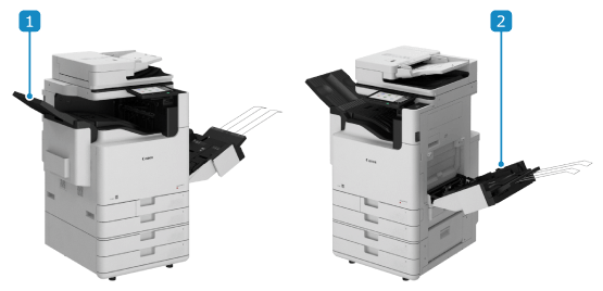
 Long Sheet Catch Tray-D
Outputs printed and copied paper.
Long Sheet Catch Tray-D cannot be used when the optional Staple Finisher-AB or Paper Folding/Booklet Finisher-A is installed.
When you use Long Sheet Catch Tray-D, pull the tray part up to open it.
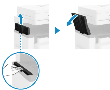
 Long Sheet Feeding Tray-B
Attach to the multi-purpose tray, and load paper. You can also load multiple sheets of paper at the same time. Loading Paper in Long Sheet Feeding Tray-B
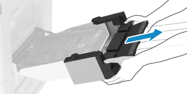
* To remove Long Sheet Feeding Tray-B, pull it out while holding the left and right edges of the tray.
Specifications
Paper Size, Type, and Basis Weight | All paper that can pass through the machine (see “About the Machine”  “Usable Paper” in the "User's Guide.") “Usable Paper” in the "User's Guide.")Paper sizes other than above: Long Sheet paper (297.0 mm x 900.0 mm (11 3/4" x 35 1/2")) Long Sheet paper (297.0 mm x 1,200.0 mm (11 3/4" x 47 1/4")) Free Size (Long Sheet) (paper from 98.0 mm x 457.3 mm to 320.0 mm x 1,300.0 mm (3 7/8" x 18" to 12 5/8" x 51 1/4")) Custom Size (paper from 98.0 mm x 457.3 mm to 320.0 mm x 1,300.0 mm (3 7/8" x 18" to 12 5/8" x 51 1/4")) |
Paper Feeding Method and Paper Capacity | Long Sheet Feeding Tray-B 10 sheets (with horizontal length of up to 900 mm (35 1/2")) 1 sheet (with horizontal length of 900.1 mm to 1,300 mm (more than 35 1/2" to 51 1/4")) |
Output Capacity | When Long Sheet Catch Tray-D is installed 20 sheets (with horizontal length of up to 900 mm (35 1/2")) 1 sheet (with horizontal length of 900.1 mm to 1,200 mm (more than 35 1/2" to 47 1/4")) When Inner Finisher-N is installed*1 1 sheet (with horizontal length of up to 900 mm (35 1/2")) When Staple Finisher-AB or Paper Folding/Booklet Finisher-A is installed 20 sheets (with horizontal length of up to 1,300 mm (51 1/4")) |
Dimensions (W x D x H) | Long Sheet Feeding Tray-B 139 mm x 456 mm x 673 mm (5 1/2" x 18" x 26 1/2") Long Sheet Catch Tray-D 155 mm x 388 mm x 373 mm (6 1/8" x 15 1/4" x 14 3/4") |
Weight | Long Sheet Feeding Tray-B Approx. 1.3 kg (2.9 lb) Long Sheet Catch Tray-D Approx. 2.0 kg (4.4 lb) |
*1When Inner Finisher-N is installed, load Long Sheet paper cut to a width of 500 mm to 550 mm (19 3/4" to 21 5/8") in the output tray (Tray B) to prevent paper jams. Preparations for Printing on Long Sheet Paper with Inner Finisher-N Installed
Loading Paper in Long Sheet Feeding Tray-B
When you use Long Sheet paper, load the paper in the Long Sheet Feeding Tray-B.
IMPORTANT
Using curled paper can cause paper jams or printing errors.
Be sure to configure the paper type settings correctly. For details on how to configure the settings, see "Basic Operations"  "Loading Paper"
  "Specifying the Paper Size and Type" in the "User's Guide."
* The image quality may be degraded if the settings are not configured properly, particularly when you use special paper such as Heavy paper. In addition, the fixing assembly may become dirty or a paper jam may occur, and repair by your service representative may be required.
 "Loading Paper"
  "Specifying the Paper Size and Type" in the "User's Guide."
 * The image quality may be degraded if the settings are not configured properly, particularly when you use special paper such as Heavy paper. In addition, the fixing assembly may become dirty or a paper jam may occur, and repair by your service representative may be required.
You cannot staple paper, fold paper, or use other finishing functions.
You cannot print on Long Sheet paper when [Settings/Registration]  [Function Settings]
  [Printer]
  [Printer Settings]
  [Custom Settings]
  [Print Quality]
  [Resolution] is set to [1200 dpi].
 [Function Settings]
  [Printer]
  [Printer Settings]
  [Custom Settings]
  [Print Quality]
  [Resolution] is set to [1200 dpi].
Install the optional Long Sheet output tray or the finisher to prevent paper from falling out of the output tray. Names of Parts and Their Functions
1
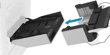
Attach the Long Sheet feeding tray to the multi-purpose tray.
2
Slide the paper guides to the outside.
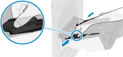
Set the width of the paper guides slightly wider than the width of the paper.
3
Load the paper with the print side face down.
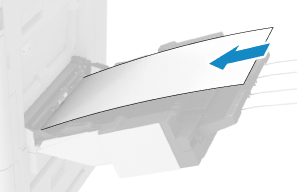
Insert the paper until the edge of the paper is against the paper tray.
You can load up to 10 sheets of paper with a horizontal length of 457.3 mm to 900 mm (18" to 35 1/2"). When you use paper wider than this, load one sheet at a time.
* Some types of paper can only be loaded one sheet at a time, regardless of the size.
* Some types of paper can only be loaded one sheet at a time, regardless of the size.
If you load more paper than the load limit, a misfeed or paper jam may occur.
When You Want to Improve the Print Precision

You can load paper correctly by aligning the paper edges with the markings on the Long Sheet feeding tray.
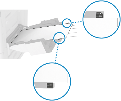
Make sure that the gap at the near edge of the paper is approximately the same size as the one at the far edge.
Make sure that the edges of the paper are parallel to the paper guides.
4
Align the paper guides with the width of the paper.
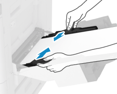
Use both hands to position the paper guides so that they match the width of the paper exactly.
Paper guides that are aligned and are too loose or too tight can cause misfeeds or a paper jam.
5
Set the paper size and type.
By default, when the machine detects paper loaded in the multi-purpose tray, the screen for setting the paper is displayed on the control panel. Set the paper size and type each time you load paper.
Press [Change Paper Size]  [Other Size] and select the size of the loaded Long Sheet paper.
 [Other Size] and select the size of the loaded Long Sheet paper.
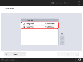
Support for Long Sheet Paper in the Paper Size Settings When Registering a New Paper Type for the Multi-Purpose Tray
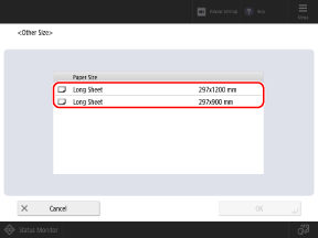
You can now configure the Long Sheet paper size settings when you register a new paper type for the multi-purpose tray. On the paper settings screen for the multi-purpose tray, you can press [Adjust/Register New Paper]  [Standard Size]
  [Other Size] and select the size of the loaded Long Sheet paper.
 [Standard Size]
  [Other Size] and select the size of the loaded Long Sheet paper.
Preparations for Printing on Long Sheet Paper with Inner Finisher-N Installed
Make the following preparations when you print on Long Sheet paper with Inner Finisher-N installed.
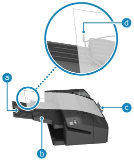
Pull out the auxiliary tray ( ) to prevent paper from falling out of the output tray.
 ) to prevent paper from falling out of the output tray.
Remove all paper output to the output tray (Tray A) ( ).
).
 ).
).To prevent paper jams, load Long Sheet paper cut to a width of 500 mm to 550 mm (19 3/4" to 21 5/8") against the support guide ( ) of the output tray (Tray B). At this time, make sure that the Long Sheet paper is seated on the end of the wire frame (
 ).
).
 ) of the output tray (Tray B). At this time, make sure that the Long Sheet paper is seated on the end of the wire frame (
 ).
).Adjusting the Print Position for Long Sheet Paper
You can now adjust the print position for Long Sheet paper. Measure the shift amount of the image on the test page, and enter the measured values to perform adjustment.
You can select the adjustment items according to the problems.
You can select the adjustment items according to the problems.
When you want to adjust multiple items, you can more easily align the print position on both sides of the paper by performing the adjustments in the following order:
When printed image is slanting diagonally (Correct Image Misalignment)
When printed image is distorted like a parallelogram (Correct Distortion (Parallelogram))
When printed image is distorted like a trapezoid (Correct Distortion (Trapezoid))
When printed image is enlarged or reduced (Adjust Image Size)
When image position is shifted left or right according to the feed direction (Adjust Left Edge Alignment)
When image position is shifted toward the leading or trailing edge according to the feed direction (Adjust Lead Edge Alignment)
Step 1: Registering the Paper Type
Register the paper type for which you want to adjust the print position as a custom paper type. For details on how to register paper types, see "Adjustment and Maintenance"  "Registering Frequently Used Paper Types" in the "User's Guide."
 "Registering Frequently Used Paper Types" in the "User's Guide."
* You can skip this step if the paper type is already registered. Proceed to Step 2.
Step 2: Printing a Test Page
Obtain the Long Sheet test page from the online manual site, and print it on both sides of the paper.
The front side of the test page has "1st side" printed on it.
To ensure accurate adjustment results, print the Long Sheet test page at 100% magnification.
Print the test page on the actual Long Sheet paper to be used.
Depending on the size of the paper to be printed, the "b," "f," "h," and "j" indicators may be printed multiple times. Perform adjustment for the locations closest to the trailing edge of the paper.
Step 3: Adjusting by Entering Measured Values
Check both the front and back sides of the test page to determine whether the print position is shifted.
If the position is shifted, measure each length on the front and back sides, and perform adjustment based on the measured values.
If the position is shifted, measure each length on the front and back sides, and perform adjustment based on the measured values.
Measure each length on the test page.
Measure the lengths on the front side and back side. The front side of the test page has "1st side" printed on it.
When Performing Correct Image Misalignment

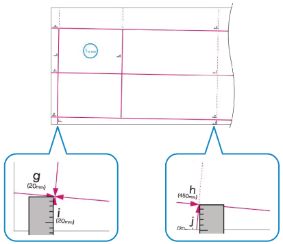
Measure the lengths of "i" and "j."
The "i" indicator is printed at the left side of the leading edge and the "j" indicator is printed at the left side of the trailing edge, according to the feed direction.
When Performing Correct Distortion (Parallelogram)

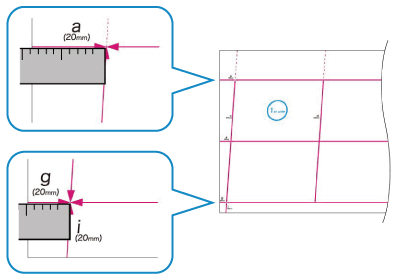
Measure the lengths of "a" and "g."
The "a" indicator is printed at the right side of the leading edge and the "g" indicator is printed at the left side of the leading edge, according to the feed direction.
When Performing Correct Distortion (Trapezoid)

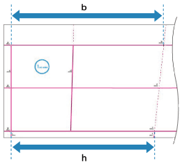
Measure the lengths of the "b" and "h" closest to the trailing edge of the paper.
The "b" indicator is printed on the right side and the "h" indicator is printed on the left side, according to the feed direction.
When Performing Adjust Image Size

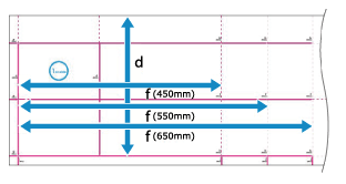
Measure the lengths of "f" and "d."
If part of the image is not printed, follow the procedure below to compare the values and calculate the enlargement or reduction ratio.
If part of "d" is missing, measure the length of "d/2" (half the length of "d"), and compare it to the prescribed value (125.0 mm).
If part of "f" is missing, measure the length of "f" closest to the trailing edge, and compare it to the corresponding prescribed value (450.0 mm, 550.0 mm, or 650.0 mm).
* If you print the test page on paper smaller than 270.0 mm x 762.0 mm (10 5/8" x 30"), part of the image will not be printed on the paper.
When Performing Adjust Left Edge Alignment

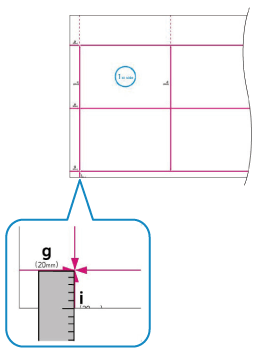
Measure the length of "i."
You can also perform adjustment by checking the value of the indicator at the bottom left. When you check the value of the indicator at the bottom left, proceed to Step 2.
When Performing Adjust Lead Edge Alignment

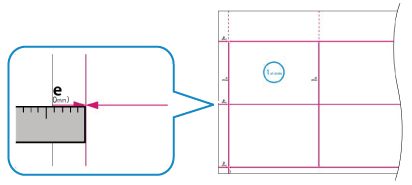
Measure the length of "e."
You can also perform adjustment by checking the value of the indicator at the leading edge according to the feed direction. When you check the value of the indicator at the bottom left, proceed to Step 2.
Enter the measured values in each item for the front side and back side.
When Performing Correct Image Misalignment

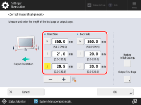
Enter the measured values in [i] and [j], enter the length that is closest to the trailing edge of the paper (360.0, 450.0, 550.0, or 650.0) in [h], and then press [OK].
When Performing Correct Distortion (Parallelogram)

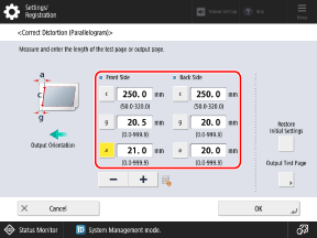
Enter the measured values in [a] and [g], enter "250.0" in [c], and then press [OK].
When Performing Correct Distortion (Trapezoid)

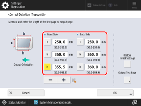
Enter the measured values in [b] and [h], enter "250.0" in [c], and then press [OK].
When Performing Adjust Image Size

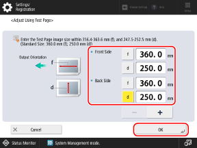
When Entering the Measured Values
Press [Adjust Using Test Page], perform the calculation below and enter the value in [f], enter the measured value in [d], and then press [OK]  [OK].
[OK].
Prescribed value (360.0 mm) ÷ Measurement position (450.0 mm, 550.0 mm, or 650.0 mm) x Measured "f" value
 [OK].
[OK]. Prescribed value (360.0 mm) ÷ Measurement position (450.0 mm, 550.0 mm, or 650.0 mm) x Measured "f" value
When Entering the Enlargement or Reduction Ratio
If part of the image is not printed on the page in Step 1, enter the calculated enlargement or reduction ratio in [Zoom (f)] and [Zoom (d)], and press [OK].
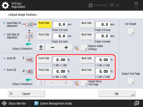
To enlarge or reduce the print image in the direction parallel to the feed direction, enter the value in [Zoom (f)].
To enlarge or reduce the print image in the direction perpendicular to the feed direction, enter the value in [Zoom (d)].
You can press [±] to switch the entered value between positive and negative.
When Performing Adjust Left Edge Alignment

When Entering the Measured Values
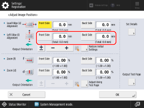
In [Left Edge (i) Alignment], enter the amount of difference between the prescribed value (20.0 mm) and the length of "i" measured in Step 1, and then press [OK].
If the measured length of "i" is 21.5 mm, enter -1.5 mm.
If the measured length of "i" is 18.5 mm, enter +1.5 mm.
You can press [±] to switch the entered value between positive and negative.
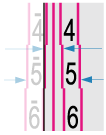
When Adjusting Based on the Indicator at the Bottom Left of the Test Page
Check the amount of the shift between the paper edge and the center line of the indicator, enter the corresponding value, and press [OK].
When the center line of the indicator is outside the paper edge (when the center line of the indicator is not printed on the page), set a positive (+) value. The print position moves toward the right edge according to the feed direction.
Example: If the center line of the indicator on the front side is 0.4 mm outside the edge of the paper, set [Front Side] to "0.4 mm."
Example: If the center line of the indicator on the front side is 0.4 mm outside the edge of the paper, set [Front Side] to "0.4 mm."
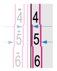
When the center line of the indicator is inside the paper edge, set a negative (-) value. The print position moves toward the left edge according to the feed direction.
Example: If the center line of the indicator on the front side is 0.6 mm inside the edge of the paper, set [Front Side] to "-0.6 mm."
Example: If the center line of the indicator on the front side is 0.6 mm inside the edge of the paper, set [Front Side] to "-0.6 mm."
When Performing Adjust Lead Edge Alignment

When Entering the Measured Values
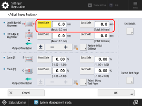
In [Lead Edge (e) Alignment], enter the amount of difference between the prescribed value (20.0 mm) and the length of "e" measured in Step 1, and then press [OK].
If the measured length of "e" is 21.0 mm, enter -1.0 mm.
If the measured length of "e" is 19.0 mm, enter +1.0 mm.
You can press [±] to switch the entered value between positive and negative.
When Adjusting Based on the Indicator at the Leading Edge of the Test Page
Check the amount of the shift between the paper edge and the center line of the indicator, enter the corresponding value, and press [OK].
When the center line of the indicator is outside the paper edge (when the center line of the indicator is not printed on the page), set a positive (+) value. The print position moves toward the trailing edge according to the feed direction.
Example: If the center line of the indicator on the front side is 0.4 mm outside the edge of the paper, set [Front Side] to "0.4 mm."
Example: If the center line of the indicator on the front side is 0.4 mm outside the edge of the paper, set [Front Side] to "0.4 mm."

When the center line of the indicator is inside the paper edge, set a negative (-) value. The print position moves toward the leading edge according to the feed direction.
Example: If the center line of the indicator on the front side is 0.6 mm inside the edge of the paper, set [Front Side] to "-0.6 mm."
Example: If the center line of the indicator on the front side is 0.6 mm inside the edge of the paper, set [Front Side] to "-0.6 mm."

Print the test page again, and check the adjustment results.
When Performing Correct Image Misalignment, Correct Distortion (Parallelogram), or Correct Distortion (Trapezoid)

1
Select [Correct Image Misalignment], [Corr. Distortion (Parallelogram)], or [Corr. Distortion (Trapezoid)].
2
Select [Output Test Page].
3
Set the number of test page copies, and press [Next].
4
Select the paper source loaded with the paper to be adjusted.
5
Press [Start Printing].
The test page(s) is printed.
When Performing Adjust Image Size, Adjust Left Edge Alignment, or Adjust Lead Edge Alignment

1
Select [Do Not Use Scanner].
2
Select [Output Test Page].
3
Set the number of test page copies, and press [Next].
4
Select the paper source loaded with the paper to be adjusted.
5
Press [Start Printing].
The test page(s) is printed.
4
If further adjustment is needed, repeat Steps 1 to 3.
* When you display the [Adjust Image Position] screen after performing Adjust Left Edge Alignment or Adjust Lead Edge Alignment, the value on the screen is reset to "0.0 mm," but the previously set value is retained. If you want to repeat the adjustment, check the indicator on the reprinted test page and set that value.
5
Press [OK]  [Close].
 [Close].
NOTE
If you want to reset the retained adjustment values to the initial values and perform the adjustment again, press [Restore Initial Settings] on the screen for setting the values.
How to Remove Long Sheet Paper Jammed Inside the Main Unit
Remove the Long Sheet paper jammed inside the main unit. Follow the instructions on the control panel to check the location of the paper jam and remove the jammed paper.
If the paper tears, be sure to remove all parts so that no pieces remain.
If you cannot remove the paper, do not try to remove it forcibly. Check the control panel and remove the jammed paper at another location.
If the paper tears, be sure to remove all parts so that no pieces remain.
If you cannot remove the paper, do not try to remove it forcibly. Check the control panel and remove the jammed paper at another location.
1
Remove any paper loaded in the multi-purpose tray.
2
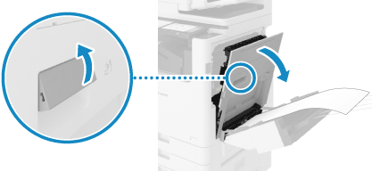
Pull the lever and open the right cover of the main unit.
3
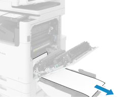
If paper is jammed in the multi-purpose tray, gently pull it out in the direction of the arrow.
4
Check whether paper is jammed in the fixing assembly.
If You Cannot Grasp the Top Edge of the Paper

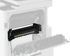
1
Hold the green lever and open the fixing assembly.
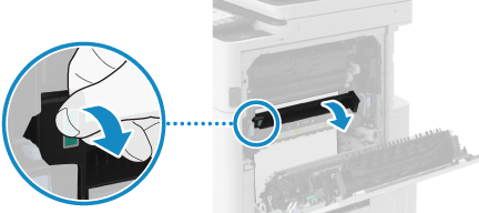
2
Gently pull out the paper in the direction of the arrow until the top edge of the paper comes out.
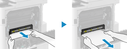
3
Gently pull out the remaining paper in the direction of the arrow.
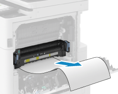
4
Close the fixing assembly.
If You Can Grasp the Top Edge of the Paper

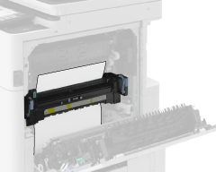
1
Hold the green lever and open the fixing assembly.
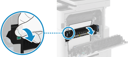
2
Gently pull out the paper in the direction of the arrow.
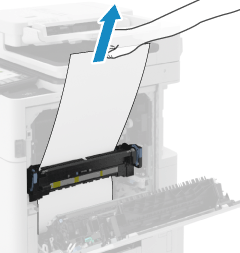
3
Close the fixing assembly.
5
Check whether paper is jammed in the output unit.
If Paper Is Partially Jammed in the Output Unit

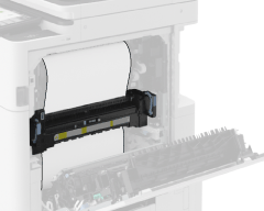
1
Hold the green lever and open the fixing assembly.
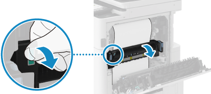
2
If the edge of the paper has entered at the top, pull the paper out slowly in the direction of the arrow until the edge comes out.
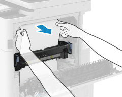
3
Gently pull out the remaining paper in the direction of the arrow.

4
Close the fixing assembly.
If Only the Edge of the Paper Is Coming out of the Output Unit

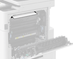
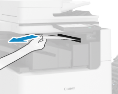
1
Gently pull out the paper from the output tray side in the direction of the arrow.
6
Gently close the right cover of the main unit until you hear a click.
When the paper jam is cleared, the screen indicating a paper jam disappears, and printing resumes automatically. If a screen indicating a paper jam at a different location appears, continue following the instructions on the screen to remove the jammed paper.
NOTE
If Paper Jams Occur Repeatedly
Check the status of the machine and paper. For details, see "Troubleshooting"  "Paper and Staple Jams"
  "Paper Jams That Occur Repeatedly" in the "User's Guide."
 "Paper and Staple Jams"
  "Paper Jams That Occur Repeatedly" in the "User's Guide."