Adjusting Left Edge Alignment of the Image
In the feeding direction, if the image position on the output paper is moved left and right from the correct position, the misaligned image position may be corrected by adjusting the margin on the left edge of the paper.
NOTE |
You can also make the adjustment by using the guide sheet. (See "Adjusting the Image Position Using the Guide Sheet.") |
1.
Press  (Settings/Registration).
(Settings/Registration).2.
Press [Preferences] → [Paper Settings] → [Paper Type Management Settings].
3.
Select the paper type that you want to edit from the list → press [Details/Edit].
4.
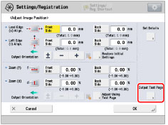
Press [Change] for <Adjust Image Position>.
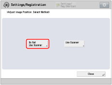
5.
Press [Do Not Use Scanner].
If you enter the difference from the measured length of the test page:
NOTE |
To adjust the image position on long sheets, print out a long sheet test page. The adjustment can be made more efficiently than with the test page printed out by [Output Test Page] under <Adjust Image Position>. (The long sheet test page is available from the online manual site.) |
Press [Output Test Page].
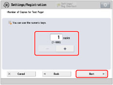
Enter the number of test pages to make → press [Next].
NOTE |
If the image position varies greatly, the accuracy of correction may be improved by printing several test pages and using an average of the measured length. |
Select a paper source that contains a custom paper type → press [Start Printing].
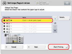
The test page is printed.
Return to the <Adjust Image Position> screen and measure the length of ‘i’ on front and back sides of the printed test page.
Standard size | Long sheet |
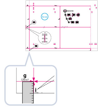 | 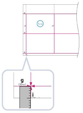 |
Default value: ‘i’ = 20.0 mm
Enter the difference in length between the measured value of ‘i’ and the default value (20 mm) for front and back sides.
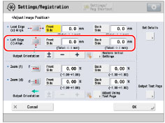
For example, if the measured length of ‘i’ is 21.5 mm, enter - 1.5 mm for <Left Edge (i) Align.>.
For example, if the measured length of ‘i’ is 18.5 mm, enter + 1.5 mm for <Left Edge (i) Align.>.
The difference of 1.5 mm between the measured length and the default value is corrected.
Press [OK].
As necessary, try printing the test page again and then check the correction amount.
If you correct the position using any printed images:
Check the image position on the output paper.
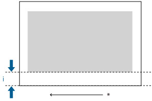
* Feeding Direction
Measure the length of 'i', which is the distance from the left edge of the printed area to the left edge of the paper, and enter the difference from the default value (20 mm).
For example, if the measured length of ‘i’ is 21.0 mm, enter - 1.0 mm for <Left Edge (i) Align.>.
For example, if the measured length of ‘i’ is 19.0 mm, enter + 1.0 mm for <Left Edge (i) Align.>.
The 1.0 mm difference between the measured value and the default value is corrected.
Press [OK].
As necessary, try printing the paper again and then check the correction amount.
6.
Press [OK].
IMPORTANT |
When you open the screen again after you close the screen by pressing [OK], the values on screen are returned to '0'. However, the adjusted value is still effective in each Total field. If you repeat the step, check the length of 'i' on the new test page and enter the new value. |
NOTE | |||||||||
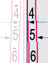
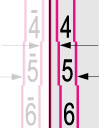
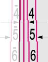
To restore the accumulated value, press [Restore Initial Settings]. You can also correct the image position by using the value of register marks shown below. Check whether the center line of the register mark and the edge of the test page are aligned, and adjust the image position as follows: If the center line of the register mark overlaps the edge of the test page exactly, it is unnecessary to adjust the image position. If the center line of the register mark is outside the edge of the test page (the center line of the register mark is NOT printed), check to see which register mark's number the test page line is next to, and input the positive value. If the center line of the register mark is inside the edge of the test page, check to see which register mark's number the test page line is next to, and input the negative value.
|