Adjusting the Image Position
You can adjust the image position quickly by using the guide sheet. In addition, if the printed image is misaligned on the output paper after printing or copying, you can adjust the image position by confirming the test pages and specifying the setting values for individual adjustment setting items.
You can also adjust the image position for the long sheet.
Adjusting Image Position by Using the Guide Sheet
Adjust the image position by using the guide sheet. The following adjustments can be made with use of the guide sheet. (See "Adjusting the Image Position Using the Guide Sheet.")
Correction for image misalignment
Correction for distortion (parallelogram)
Correction for distortion (trapezoid)
Adjustment for zoom ratio
Adjustment for left edge alignment
Adjustment for lead edge alignment
Adjusting Individual Image Position Setting by Using the Test Page
When the printed image is slanted:
Perform the Correct Image Misalignment mode. (See "Correct Image Misalignment.")
When the printed image is distorted like a parallelogram:
Perform the Correct Distortion (Parallelogram) mode. (See "Correct Distortion (Parallelogram).")
When the printed image is distorted like a trapezoid:
Perform the Correct Distortion (Trapezoid) mode. (See "Correct Distortion (Trapezoid).")
When the printed image is enlarged or reduced:
Adjust the zoom ratio of the image. (See "Adjusting the Zoom Ratio of the Image.")
When the printed image is misaligned vertically or horizontally:
Adjust the left edge or lead edge alignment. (See "Adjusting Left Edge Alignment of the Image" and "Adjusting Lead Edge Alignment of the Image.")
Correct image misalignment → correct distortion (parallelogram) → correct distortion (trapezoid) → adjust the zoom ratio → adjust the left edge alignment → adjust the lead edge alignment.
NOTE |
You cannot change the image position on paper which is being used for copying/printing jobs. The image positions on the first side and second side may match each other, if you adjust the image position in order shown below. Correct image misalignment → correct distortion (parallelogram) → correct distortion (trapezoid) → adjust the zoom ratio → adjust the left edge alignment → adjust the lead edge alignment. To adjust the image position on long sheets, print out a long sheet test page. The adjustment can be made more efficiently than with the test page printed out by [Output Test Page] under <Adjust Image Position>. (The long sheet test page is available from the online manual site.) |
IMPORTANT |
Before making adjustments, clean the platen glass and the back of the feeder. |
Test Page
NOTE |
The test page, which you printed for correct distortion (parallelogram), can also be used for correct distortion (trapezoid), adjust the zoom ratio, adjust the left edge alignment, and adjust the lead edge alignment. If you adjust the image position in the order of correct image misalignment → correct distortion (parallelogram) → correct distortion (trapezoid) → adjust the zoom ratio → adjust the left edge alignment → adjust the lead edge alignment, you need to print a test page when you make the adjustment shown below. Before you start the correct image misalignment. Before you start the correct distortion (parallelogram). |
Standard Size Test Page
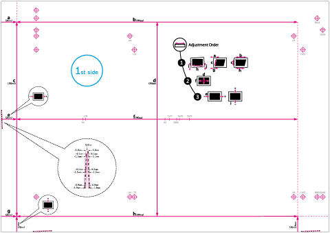
The test page used when you adjust the image position is described below. The following shows the test page which is printed on A3 paper.
(The side with "1st side" printed is the front side. The side with nothing printed on it is the back side.)
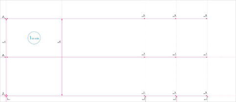
Long Sheet Test Page
The long sheet test page used when you adjust the image position of long sheets is described below. The following shows the long sheet test page which is printed on user-defined size (330.2 x 762 mm) paper. (The side with "1st side" printed is the front side. The side with nothing printed on it is the back side.)
NOTE |
'b', 'f', 'h', and 'j' may be printed multiple times depending on the size of the output paper. Make the adjustment at the position nearest to the tail edge of the paper. |
IMPORTANT |
Before making adjustments, print the long sheet test page* with the following conditions. If it is not printed properly, the adjustments may not be accurate. Set the zoom ratio to 100% (same size). Use the paper to use for the output to print the long sheet test page. * The long sheet test page is available from the online manual site. |
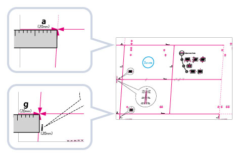
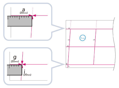
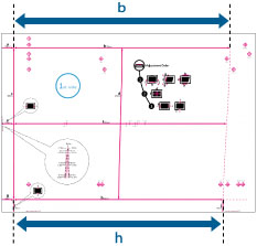
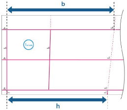
Marks for Correct Image Misalignment, Correct Distortion (Parallelogram), and Correct Distortion (Trapezoid)
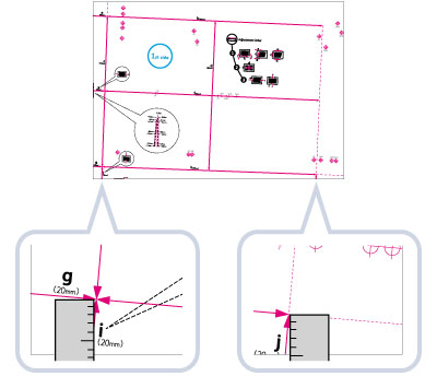
The 'i' and 'j' marks are used for Correct Image Misalignment, 'a' and 'g' marks are used for Correct Distortion (Parallelogram), and 'b' and 'h' marks are used for Correct Distortion (Trapezoid).
If the printed image is misaligned, you can adjust the image position by specifying the Correct Image Misalignment mode. The image position is corrected after you measure and enter the length of the 'i' and 'j' marks (for the long sheet: the length of the 'i' mark and the 'j' and 'h' marks that are closest to the tail edge of the paper).
Standard size | Long sheet |
 |  |
If the printed image is distorted like a parallelogram, you can adjust the angle of the image by specifying the Correct Distortion (Parallelogram) mode. The angle of the image is corrected after you measure and enter the length of the 'a' and 'g' marks.
Standard size | Long sheet |
 |  |
If the printed image is distorted like a trapezoid, you can adjust the angle of the image by specifying the Correct Distortion (Trapezoid) mode. The angle of the image is corrected after you measure and enter the length of the 'b' and 'h' marks (for the long sheet: the length of the 'b' and 'h' marks that are closest to the tail edge of the paper).
Standard size | Long sheet |
 |  |
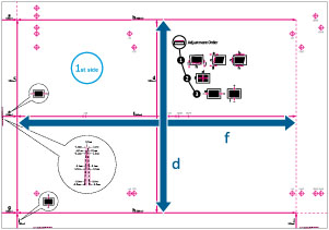
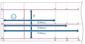
Register Marks for Adjusting the Zoom Ratio
The zoom ratio of printed area is shown by 'f' and 'd' on the test page. When the setting is correct, the length of 'f' will be 360 mm and the length of 'd' will be 250 mm (for the long sheet: the length of 'f' will be 450.0 mm, 550.0 mm, 650.0 mm and the length of 'd' will be 250 mm).
Standard size | Long sheet |
 |  |
NOTE |
Standard sizeIf you print the test page using paper smaller than 10 5/8" x 15" (270 mm x 380 mm), you cannot measure the length of 'f' and 'd' as the entire image will not be printed on the paper. In this case, calculate the expanding/reducing percentage by comparing the measured length of 'f/2' and 'd/2' with the default values (f/2: 180 mm, d/2: 125 mm). By using the calculated percentage, adjust the zoom ratio. (See "Adjusting the Zoom Ratio of the Image.") 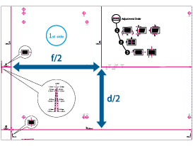 An Example of the Test Page Lacking an Image Long sheetIf you print the long sheet test page using paper smaller than 10 5/8" x 30" (270 mm x 762 mm), the entire image will not be printed on the paper. Calculate the expanding/reducing percentage by comparing the measured length of 'd/2' with the default value (d/2: 125 mm). If 'f' is not printed entirely, measure the length of 'f' that is closest to the tail edge of the paper, and calculate the expanding/reducing percentage by comparing the measured length with the default values (f=450 mm, 550 mm, 650 mm). By using the calculated percentage, adjust the zoom ratio. (See "Adjusting the Zoom Ratio of the Image.") 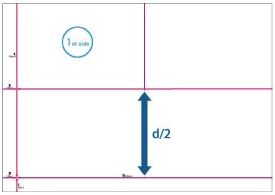 An Example of the Long Sheet Test Page Lacking an Image. |
Register Marks on the Left Edge and Lead Edge
If the printed image on the output paper is moved left and right from the correct position in the feeding direction, you can adjust the position by measuring the length of 'i’ and entering the value.
If the printed image on the output paper is moved back and forth from the correct position in the feeding direction, you can adjust the position by measuring the length of ‘e’ and entering the value.
Standard size | Long sheet |
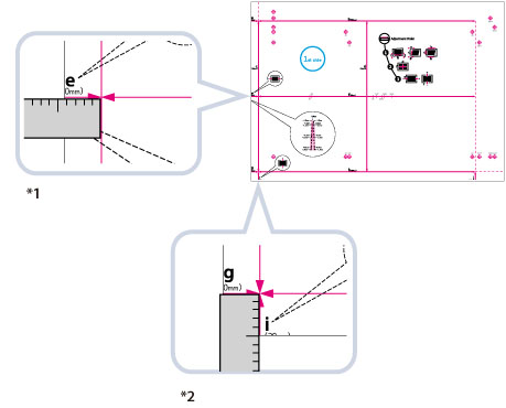 | 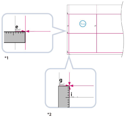 |
*1 Adjust the Lead Edge Alignment
*2 Adjust the Left Edge Alignment