Adjusting the Print Position by Entering Measured Values
Measure the shift amount of the image on the test page or any printed page, and enter the measured values to perform adjustment.
You can select the adjustment items according to the problems.
You can select the adjustment items according to the problems.
When you want to adjust multiple items, you can more easily align the print position on both sides of the paper by performing the adjustments in the following order:
When printed image is slanting diagonally (Correct Image Misalignment)
When printed image is distorted like a parallelogram (Correct Distortion (Parallelogram))
When printed image is distorted like a trapezoid (Correct Distortion (Trapezoid)) (C7100 Series only)
When printed image is enlarged or reduced (Adjust Image Size)
When image position is shifted left or right according to the feed direction (Adjust Left Edge Alignment)
When image position is shifted toward the leading or trailing edge according to the feed direction (Adjust Lead Edge Alignment)
* You cannot perform Adjust Image Size using any other printed page.
Step 1: Registering the Paper Type
Register the paper type for which you want to adjust the print position as a custom paper type. Registering Frequently Used Paper Types
* You can skip this step if the paper is already registered. Proceed to Step 2.
Step 2: Printing a Test Page
Print a test page on both sides of the paper using the control panel. Usable Paper for 2-Sided Printing
You cannot print the test page using Remote UI from a computer.
For C5100 Series, Administrator or DeviceAdmin privileges are required.
You cannot print the test page using Remote UI from a computer.
For C5100 Series, Administrator or DeviceAdmin privileges are required.
* You can skip this step if you use a printed page other than the test page. Proceed to Step 3. Step 3: Adjusting by Entering Measured Values
* If you want to perform adjustment for Long Sheet paper, print the dedicated test page on both sides of the paper, and proceed to Step 3. Step 3: Adjusting by Entering Measured Values
You can download the dedicated test page from the online manual site.
https://oip.manual.canon/
https://oip.manual.canon/
The front side of the test page has "1st side" printed on it.
To ensure accurate adjustment results, print the Long Sheet test page at 100% magnification.
Print the test page on the actual Long Sheet paper to be used.
Depending on the size of the paper to be printed, the "b," "f," "h," and "j" indicators may be printed multiple times. Perform adjustment for the locations closest to the trailing edge of the paper.
Required Preparations
Load the paper you want to adjust.
* Use up to 10 sheets of paper for printing the test page.
1
Log in to the machine as an administrator (for C5100 Series). Logging In to the Machine
2
On the control panel, press [ Settings/Registration] in the [Home] screen or other screen. [Home] Screen
 Settings/Registration] in the [Home] screen or other screen. [Home] Screen
The [Settings/Registration] screen is displayed.
3
Press [Preferences]  [Paper Settings]
  [Paper Type Management Settings].
 [Paper Settings]
  [Paper Type Management Settings].
The [Paper Type Management Settings] screen is displayed.
4
Select the registered custom paper, and press [Details/Edit].
The [Details/Edit] screen is displayed.
5
Press [Change] for [Adjust Image Position].
The screen for selecting the adjustment method is displayed.
6
Press [Do Not Use Scanner].
The [Adjust Image Position] screen is displayed.
7
Print a test page.
Print the test page according to the items you want to adjust.
* The test page printed for Correct Distortion (Parallelogram) can also be used for the other adjustment items except Correct Image Misalignment.
When Performing Correct Image Misalignment, Correct Distortion (Parallelogram), or Correct Distortion (Trapezoid)

1
Select [Set Details].
2
Select [Correct Image Misalignment], [Corr. Distortion (Parallelogram)], or [Corr. Distortion (Trapezoid)].
3
Select [Output Test Page].
4
Set the number of test page copies, and press [Next].
5
Select the paper source loaded with the paper to be adjusted.
6
Press [Start Printing].
The test page(s) is printed.
When Performing Adjust Image Size, Adjust Left Edge Alignment, or Adjust Lead Edge Alignment

1
Select [Output Test Page].
2
Set the number of test page copies, and press [Next].
3
Select the paper source loaded with the paper to be adjusted.
4
Press [Start Printing].
The test page(s) is printed.
Step 3: Adjusting by Entering Measured Values
Check both the front and back sides of the test page or a printed page to determine whether the print position is shifted.
If the position is shifted, measure each length on the front and back sides, and perform adjustment based on the measured values.
If the position is shifted, measure each length on the front and back sides, and perform adjustment based on the measured values.
Measure each length on the test page or a printed page.
Measure the lengths on the front side and back side. The front side of the test page has "1st side" printed on it.
When Performing Correct Image Misalignment

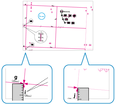
Test page (standard size)
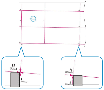
Test page (Long)
Other printed page
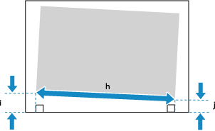
Measure the lengths of "i" and "j."
On the test page, the "i" indicator is printed at the left side of the leading edge and the "j" indicator is printed at the left side of the trailing edge, according to the feed direction.
When you use a printed page other than the test page, also measure the length of "h."
When Performing Correct Distortion (Parallelogram)

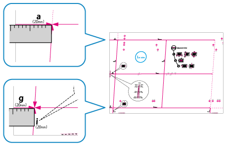
Test page (standard size)
Test page (Long)
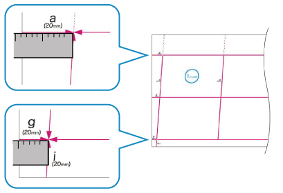
Other printed page
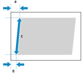
Measure the lengths of "a" and "g."
On the test page, the "a" indicator is printed at the right side of the leading edge and the "g" indicator is printed at the left side of the leading edge, according to the feed direction.
When you use a printed page other than the test page, also measure the length of "c."
When Performing Correct Distortion (Trapezoid) (C7100 Series Only)

Test page (standard size)
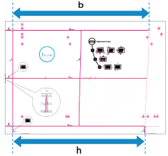
Test page (Long)
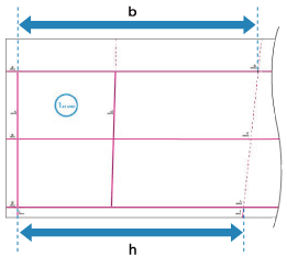
Other printed page
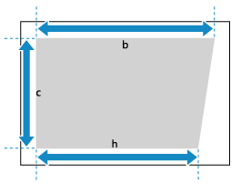
Measure the lengths of "b" and "h." For Long Sheet paper, measure the lengths of the "b" and "h" closest to the trailing edge of the paper.
On the test page, the "b" indicator is printed on the right side and the "h" indicator is printed on the left side, according to the feed direction.
When you use a printed page other than the test page, also measure the length of "c."
When Performing Adjust Image Size

Test page (standard size)
Test page (Long)
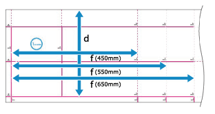
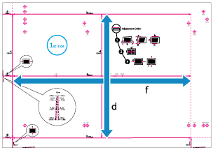
Measure the lengths of "f" and "d."
If part of the image is not printed on the test page (standard size), measure the lengths of "f/2" (half the length of "f") and "d/2" (half the length of "d"). Compare these measured values to the prescribed values (f/2: 180.0 mm, d/2: 125.0 mm) to calculate the enlargement or reduction ratio.
* If you print the test page on paper smaller than 270.0 mm x 380.0 mm (10 5/8" x 15"), part of the image will not be printed on the paper.
If part of the image is not printed on the test page (Long), follow the procedure below to compare the values and calculate the enlargement or reduction ratio.
If part of "d" is missing, measure the length of "d/2" (half the length of "d"), and compare it to the prescribed value (125.0 mm).
If part of "f" is missing, measure the length of "f" closest to the trailing edge, and compare it to the corresponding prescribed value (450.0 mm, 550.0 mm, or 650.0 mm).
* If you print the test page on paper smaller than 270.0 mm x 762.0 mm (10 5/8" x 30"), part of the image will not be printed on the paper.
When Performing Adjust Left Edge Alignment

Test page (standard size)
Test page (Long)
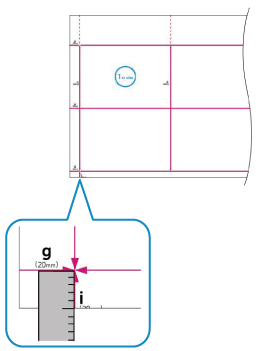
Other printed page
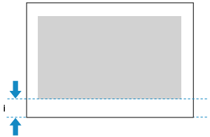
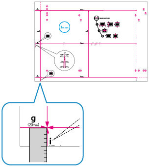
Measure the length of "i."
When you use the test page, you can also perform adjustment by checking the value of the indicator at the bottom left. When you check the value of the indicator at the bottom left, proceed to Step 2.
When you use a printed page other than the test page, "i" is at the left side of the leading edge according to the feed direction.
When Performing Adjust Lead Edge Alignment

Test page (standard size)
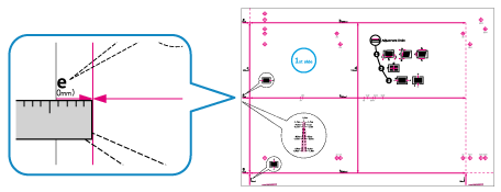
Test page (Long)
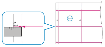
Other printed page
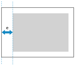
Measure the length of "e."
When you use the test page, you can also perform adjustment by checking the value of the indicator at the leading edge according to the feed direction. When you check the value of the indicator at the bottom left, proceed to Step 2.
When you use a printed page other than the test page, "e" is at the leading edge according to the feed direction.
Enter the measured values in each item for the front side and back side.
When Performing Correct Image Misalignment

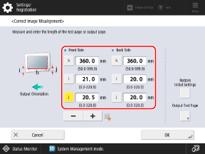
Enter the measured values in [i] and [j], enter the value indicated below in [h], and press [OK].
For test page (standard size): 360.0
For test page (Long): Value closest to trailing edge (360.0, 450.0, 550.0, or 650.0)
For other printed page: Measured value
When Performing Correct Distortion (Parallelogram)

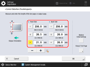
Enter the measured values in [a] and [g], enter the value indicated below in [c], and press [OK].
For test page (standard size or Long): 250.0
For other printed page: Measured value
When Performing Correct Distortion (Trapezoid) (C7100 Series Only)

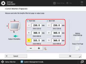
Enter the measured values in [b] and [h], enter the value indicated below in [c], and press [OK].
For test page (standard size or Long): 250.0
For other printed page: Measured value
When Performing Adjust Image Size

When Entering the Measured Values
Press [Adjust Using Test Page], enter the measured values in [f] and [d], and press [OK]  [OK].
[OK].
 [OK].
[OK].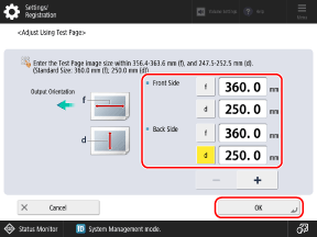
For a Long test page, perform the calculation below and enter the value in [f].
Prescribed value (360.0 mm) ÷ Measurement position (450.0 mm, 550.0 mm, or 650.0 mm) x Measured "f" value
Prescribed value (360.0 mm) ÷ Measurement position (450.0 mm, 550.0 mm, or 650.0 mm) x Measured "f" value
When Entering the Enlargement or Reduction Ratio
If part of the image is not printed on the page in Step 1, enter the calculated enlargement or reduction ratio in [Zoom (f)] and [Zoom (d)], and press [OK].
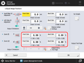
To enlarge or reduce the print image in the direction parallel to the feed direction, enter the value in [Zoom (f)].
To enlarge or reduce the print image in the direction perpendicular to the feed direction, enter the value in [Zoom (d)].
You can press [±] to switch the entered value between positive and negative.
When Performing Adjust Left Edge Alignment

When Entering the Measured Values
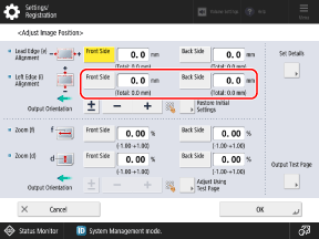
In [Left Edge (i) Alignment], enter the amount of difference between the prescribed value (20.0 mm) and the length of "i" measured in Step 1, and then press [OK].
If the measured length of "i" is 21.5 mm, enter -1.5 mm.
If the measured length of "i" is 18.5 mm, enter +1.5 mm.
You can press [±] to switch the entered value between positive and negative.
When Adjusting Based on the Indicator at the Bottom Left of the Test Page
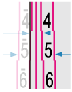
Check the amount of the shift between the paper edge and the center line of the indicator, enter the corresponding value, and press [OK].
When the center line of the indicator is outside the paper edge (when the center line of the indicator is not printed on the page), set a positive (+) value. The print position moves toward the right edge according to the feed direction.
Example: If the center line of the indicator on the front side is 0.4 mm outside the edge of the paper, set [Front Side] to "0.4 mm."
Example: If the center line of the indicator on the front side is 0.4 mm outside the edge of the paper, set [Front Side] to "0.4 mm."
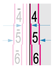
When the center line of the indicator is inside the paper edge, set a negative (-) value. The print position moves toward the left edge according to the feed direction.
Example: If the center line of the indicator on the front side is 0.6 mm inside the edge of the paper, set [Front Side] to "-0.6 mm."
Example: If the center line of the indicator on the front side is 0.6 mm inside the edge of the paper, set [Front Side] to "-0.6 mm."
When Performing Adjust Lead Edge Alignment

When Entering the Measured Values
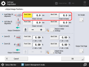
In [Lead Edge (e) Alignment], enter the amount of difference between the prescribed value (20.0 mm) and the length of "e" measured in Step 1, and then press [OK].
If the measured length of "e" is 21.0 mm, enter -1.0 mm.
If the measured length of "e" is 19.0 mm, enter +1.0 mm.
You can press [±] to switch the entered value between positive and negative.
When Adjusting Based on the Indicator at the Leading Edge of the Test Page
Check the amount of the shift between the paper edge and the center line of the indicator, enter the corresponding value, and press [OK].
When the center line of the indicator is outside the paper edge (when the center line of the indicator is not printed on the page), set a positive (+) value. The print position moves toward the trailing edge according to the feed direction.
Example: If the center line of the indicator on the front side is 0.4 mm outside the edge of the paper, set [Front Side] to "0.4 mm."
Example: If the center line of the indicator on the front side is 0.4 mm outside the edge of the paper, set [Front Side] to "0.4 mm."

When the center line of the indicator is inside the paper edge, set a negative (-) value. The print position moves toward the leading edge according to the feed direction.
Example: If the center line of the indicator on the front side is 0.6 mm inside the edge of the paper, set [Front Side] to "-0.6 mm."
Example: If the center line of the indicator on the front side is 0.6 mm inside the edge of the paper, set [Front Side] to "-0.6 mm."

Print the test page again, and check the adjustment results.
When Performing Correct Image Misalignment, Correct Distortion (Parallelogram), or Correct Distortion (Trapezoid)

1
Select [Correct Image Misalignment], [Corr. Distortion (Parallelogram)], or [Corr. Distortion (Trapezoid)].
2
Select [Output Test Page].
3
Set the number of test page copies, and press [Next].
4
Select the paper source loaded with the paper to be adjusted.
5
Press [Start Printing].
The test page(s) is printed.
When Performing Adjust Image Size, Adjust Left Edge Alignment, or Adjust Lead Edge Alignment

1
Select [Do Not Use Scanner].
2
Select [Output Test Page].
3
Set the number of test page copies, and press [Next].
4
Select the paper source loaded with the paper to be adjusted.
5
Press [Start Printing].
The test page(s) is printed.
4
If further adjustment is needed, repeat Steps 1 to 3.
* When you display the [Adjust Image Position] screen after performing Adjust Left Edge Alignment or Adjust Lead Edge Alignment, the value on the screen is reset to "0.0 mm," but the previously set value is retained. If you want to repeat the adjustment, check the indicator on the reprinted test page and set that value.
5
Press [OK]  [Close].
 [Close].
NOTE
If you want to reset the retained adjustment values to the initial values and perform the adjustment again, press [Restore Initial Settings] on the screen for setting the values.